Method And Apparatus For Processing A Video Signal

a video signal and processing method technology, applied in signal generators with optical-mechanical scanning, selective content distribution, television systems, etc., can solve problems such as video frame jitter

Active Publication Date: 2012-07-05
MICROSOFT TECH LICENSING LLC
View PDF2 Cites 10 Cited by
  • Summary
  • Abstract
  • Description
  • Claims
  • Application Information

AI Technical Summary

Benefits of technology

[0012]However, advantageously, the visual information content of the video signal is taken into account and variations in the output rate of frames from the jitter buffer are controlled considering the perceived distortion which such variations would introduce to the visual information content. The inventors have realized that the perceptual distortion caused by variations in the output rate of the frames from the jitter buffer is greater for some visual information content than for other visual information content. Variations in the output rate can be controlled to be greater for frames for which the variations will cause a lower level of perceptual distortion. The result of this is that playback speed related distortions in the video signal are much less visible (i.e. much less noticeable to a user viewing the visual information content of the video signal) compared to prior methods which do not take into account the visual information content of the video signal. Since the playback speed related distortions are less noticeable to a user, a more perceptually pleasant playback of the video signal is achieved.
[0013]Preferably, the variations in the output rate are controlled such that a significant variation in the output rate occurs only for frames for which there is a low level of motion in the visual information content. Also preferably, the variations in the output rate are controlled such that variations in the output rate are reduced as motion in the visual information content increases. The term “motion” is used to mean the amount of visual information content per frame that changes (compared to the previous frame). Variations in the output rate are less noticeable to a viewer of the video signal when they occur for sequences of frames which have a relatively low level of motion in the visual information content when they are played out. The inventors have realized that if the device at which the video signal is to be output is a mobile device then the user tends to shake the mobile device, such that the quality of motion in the video signal may be perceptually less important to the user than when the device is not a mobile device. Therefore, knowledge of whether the output device is a mobile device or not may be used to control the output rate of the video signal accordingly.
[0015]The appearance of the visual information content of frames of the video signal can be determined and used to determine the sensitivity of the frames to changes in the rate at which the frames are played out. The inventors have realized that by taking the visual information content of the frames into account when varying the rate at which the frames are played out a more perceptually pleasant playback of the video signal can be achieved.

Problems solved by technology

For example, this may be due to the timing of the frames arriving at the receiving device being disrupted by problems in the network.
However, even when a jitter buffer is used at the receiving device jitter may occur in the video frames, for example when the jitter buffer becomes completely full or completely empty.

Method used


Image

  • Method And Apparatus For Processing A Video Signal
  • Method And Apparatus For Processing A Video Signal
  • Method And Apparatus For Processing A Video Signal

Examples


Embodiment Construction

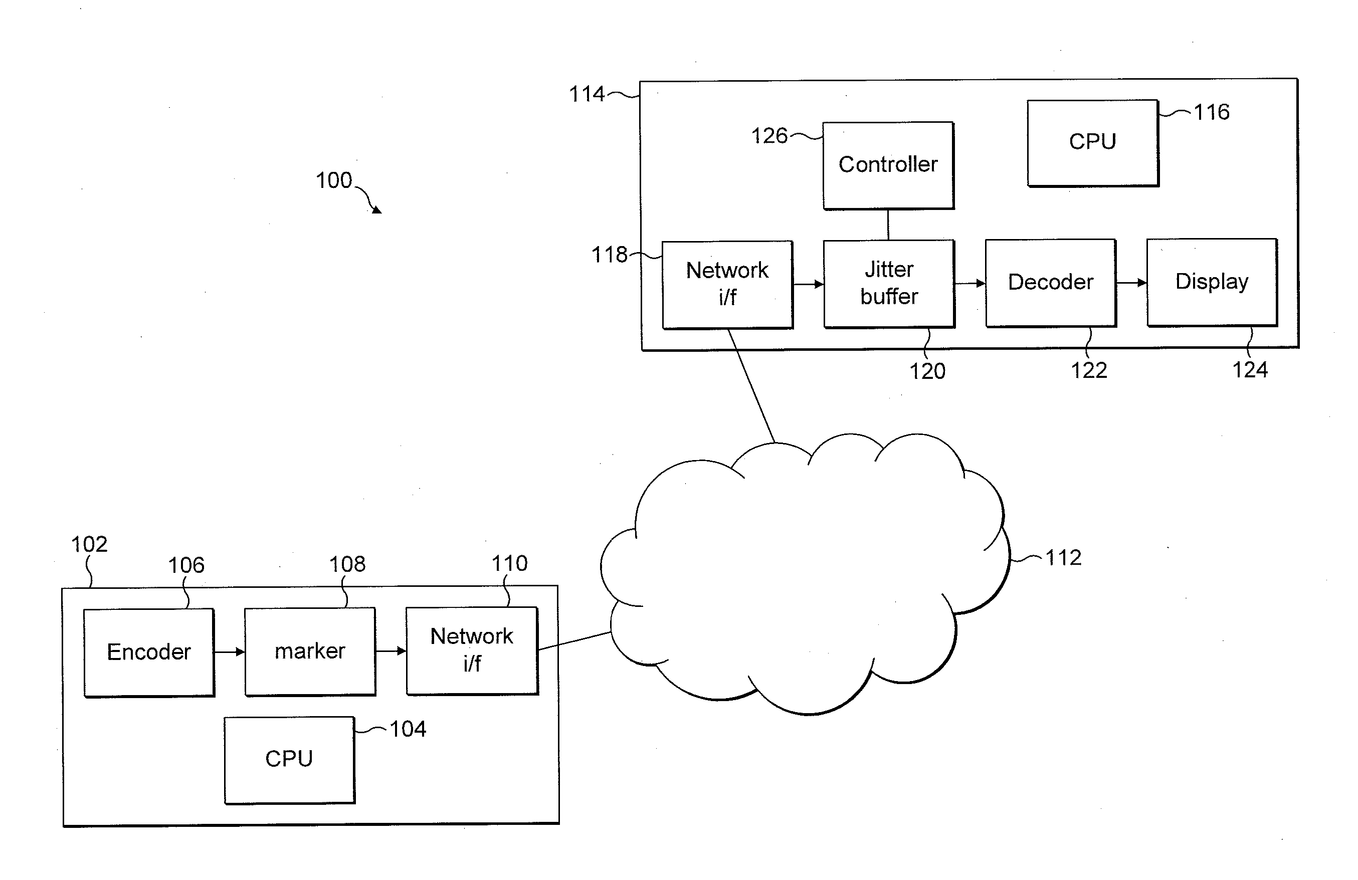
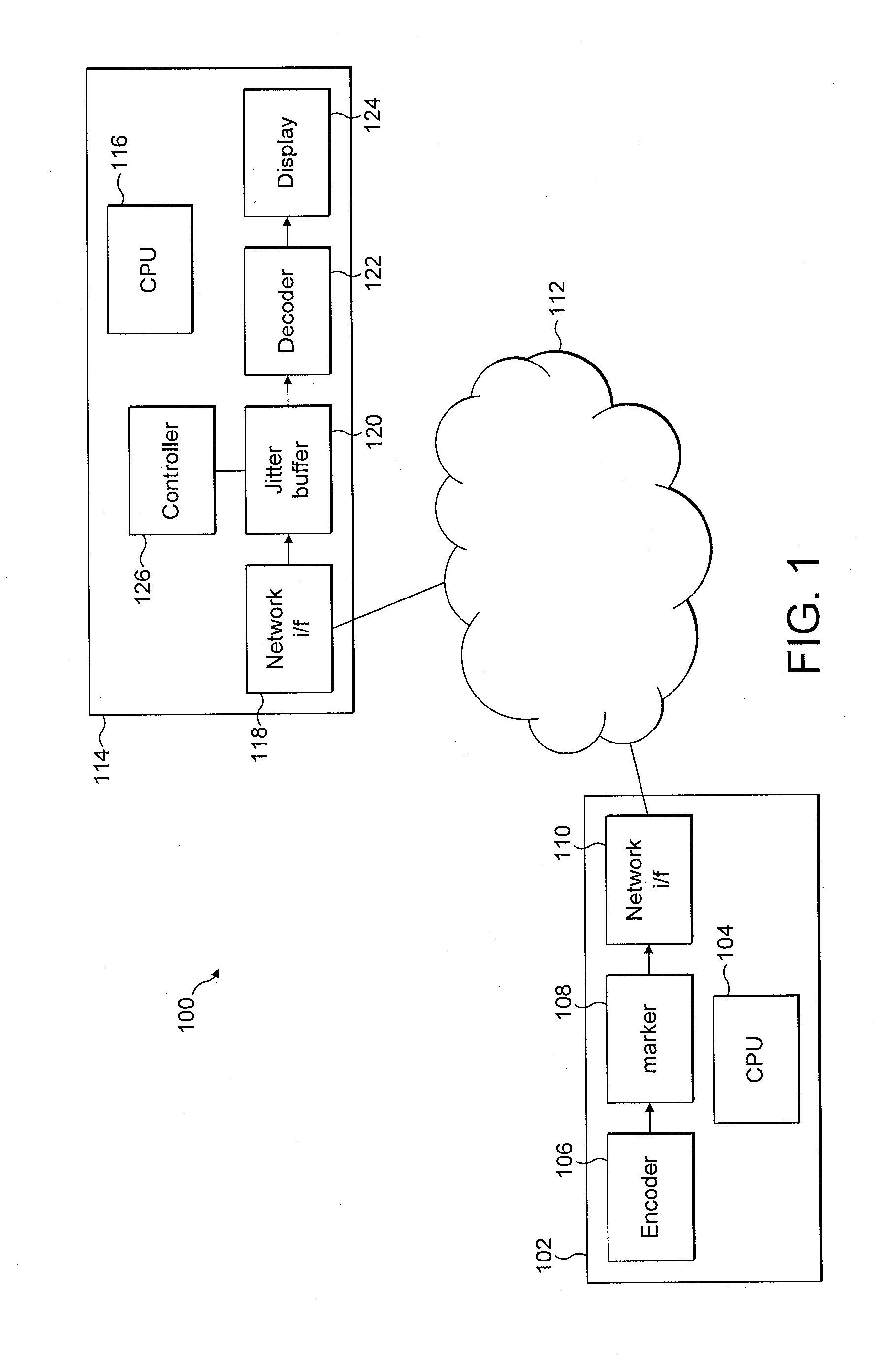
[0020]With reference to FIG. 1 there is now described a communications network 100 according to a preferred embodiment. The communications network 100 comprises a device 102 and a device 114 which can communicate with each other over the network 100 via the rest of the communications network, denoted generally as 112 in FIG. 1. The communications network 100 may, for example, be the internet. The device 102 comprises a CPU 104, an encoder block 106, a marker block 108 and a network interface block 110. The CPU 104 controls the operation of the other blocks in the device 102 as would be apparent to a person skilled in the art. An output of the encoder block 106 is coupled to an input of the marker block 108. An output of the marker block 108 is coupled to an input of the network interface block 110. The network interface block 110 is coupled to the rest of the network 112.

[0021]The device 114 comprises a CPU 116, a network interface block 118, a jitter buffer 120, a decoder block 122...


PUM


Abstract

Method, apparatus and computer program product for processing a video signal, the video signal comprising a plurality of frames, wherein the frames of the video signal are received at a jitter buffer, and the frames are output from the jitter buffer at a variable output rate to account for jitter in the received frames. Variations in the output rate are controlled in dependence upon the visual information content of the video signal, the visual information content of the video signal being the portion of the video signal that is to be displayed when the video signal is played out.

Description

RELATED APPLICATION[0001]This application claims the benefit of U.S. Provisional Application No. 61 / 428,000, filed on Dec. 29, 2010. The entire teachings of the above application are incorporated herein by reference.TECHNICAL FIELD[0002]The present invention relates to a method and apparatus for processing a video signal. In particular, the present invention relates to controlling the output rate of frames of a video signal from a jitter buffer.BACKGROUND[0003]Users can communicate with each other over a communications network by transmitting and receiving signals over the network. Advances in communications technology have resulted in a rapid increase in the number of users communicating over such networks and also in the volume of data being transferred between users in a communication. Networks now support the transmission of video signals between users. Video signals may comprise a sequence of frames which are displayed sequentially when the video signal is played out. As is kno...

Claims


Application Information

Patent Timeline
Patent Type & Authority Applications(United States)
IPC IPC(8): H04N7/00
CPCH04N21/44004H04N21/4325H04N17/004H04N5/21H04N21/8455
Inventor PLASBERG, JANJEFREMOV, ANDREI
Owner MICROSOFT TECH LICENSING LLC
Why Eureka
Try Eureka