Illumination device

a technology of a light source and a slit is applied in the field of light source, which can solve problems such as led damage, and achieve the effects of reducing unnecessary power consumption, suppressing power consumption, and reducing damage to the light emitting uni

Active Publication Date: 2012-08-23
PANASONIC INTELLECTUAL PROPERTY MANAGEMENT CO LTD
View PDF4 Cites 26 Cited by
  • Summary
  • Abstract
  • Description
  • Claims
  • Application Information

AI Technical Summary

Benefits of technology

[0011]According to the present invention, when the light emitting unit is attached to the lighting circuit, the current limiting unit limits the current flowing in the light emitting unit. Accordingly, although the light emitting unit is attached while the output voltage of the lighting circuit is not reduced, it is possible to prevent an inrush current from flowing into a light emitting unit, thereby reducing damage to the light emitting unit. Further, by suppressing the power consumed in the current limiting unit in a normal lighting mode, it is possible to reduce the unnecessary power consumption.

Problems solved by technology

Further, a large amount of current instantaneously flowing when powering, i.e., an inrush current, may not only affect circuit elements other than the LED, but also cause the noise.
However, the above-mentioned conventional illumination devices have a following problem.
The problem of the inrush current flowing into the LED does not always occur only when turning on the power.
In this case, since the LED module is attached while a voltage on the output side of the lighting circuit is not reduced, the inrush current may flow in the LED module due to the output voltage, thereby causing damage to the LED.

Method used


Image

  • Illumination device
  • Illumination device
  • Illumination device

Examples


first embodiment

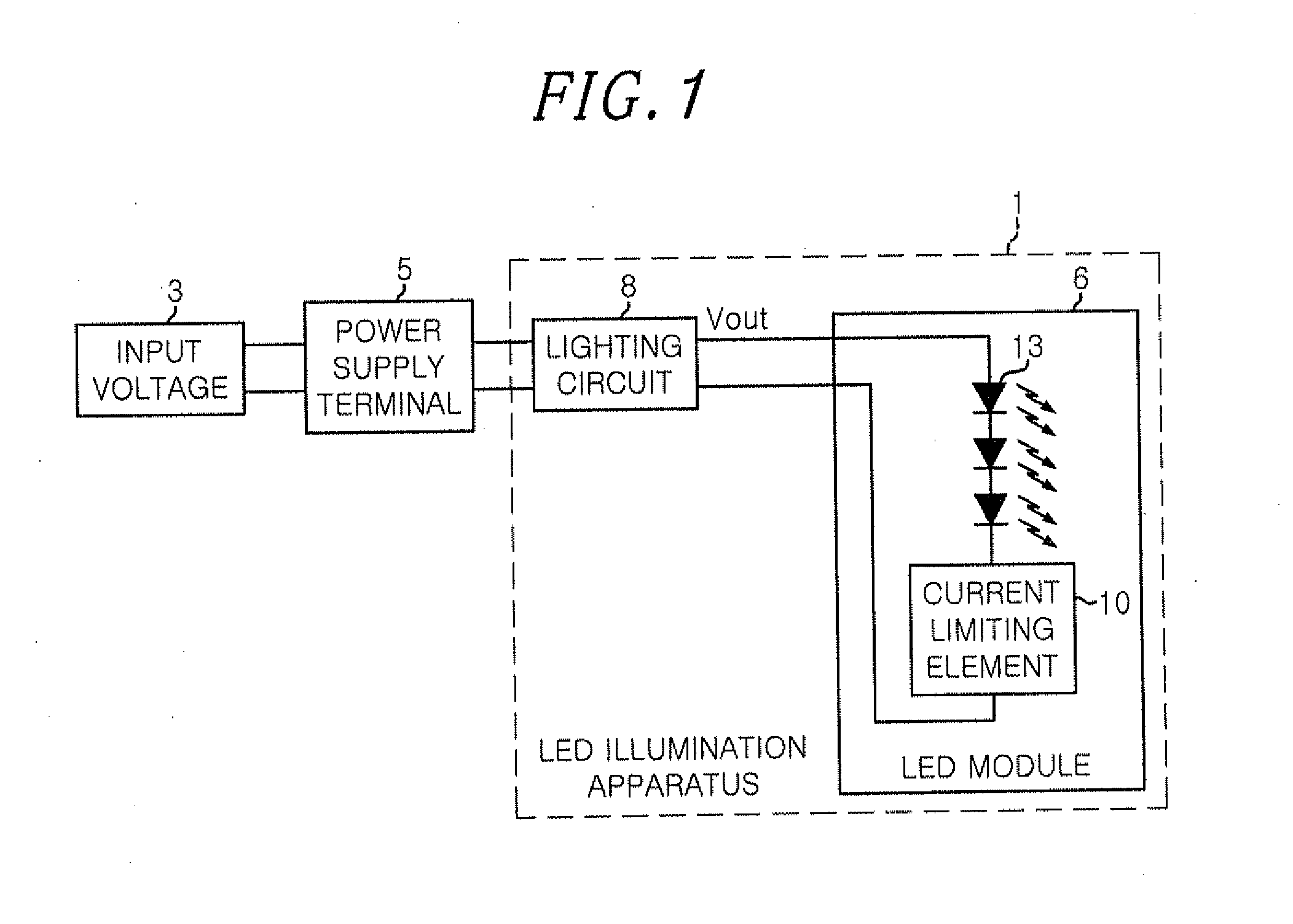
[0021]FIG. 1 schematically shows a configuration of an LED illumination apparatus in accordance with a first embodiment of the present invention. An LED illumination apparatus 1 is detachably connected to a power supply terminal 5 to which an input voltage 3 from a commercial AC or DC power source or the like is supplied. The LED illumination apparatus 1 includes a replaceable LED module 6 and a lighting circuit 8 for driving the LED module 6.

[0022]The LED module 6 includes a plurality of LEDs (light emitting element unit) 13 connected in series to each other and a current limiting element (current limiting unit) 10 connected in series to the LEDs 13.

[0023]The lighting circuit 8 generates and supplies a voltage Vout required for driving the LED module 6 serving as a load. The lighting circuit 8 includes an AC / DC converter which rectifies the input voltage from the commercial AC power source or the like, and steps up or down the input voltage to obtain an appropriate output voltage V...

second embodiment

[0050]The case where the current limiting element is connected in series to a plurality of LEDs has been described in the first embodiment.

[0051]A case where the current limiting element is connected in parallel to a plurality of LEDs will be described in a second embodiment.

[0052]FIG. 3 is a circuit diagram showing a configuration of an LED illumination apparatus in accordance with the second embodiment of the present invention. The same reference numerals are assigned to the same components as those of the first embodiment, and a description thereof will be omitted.

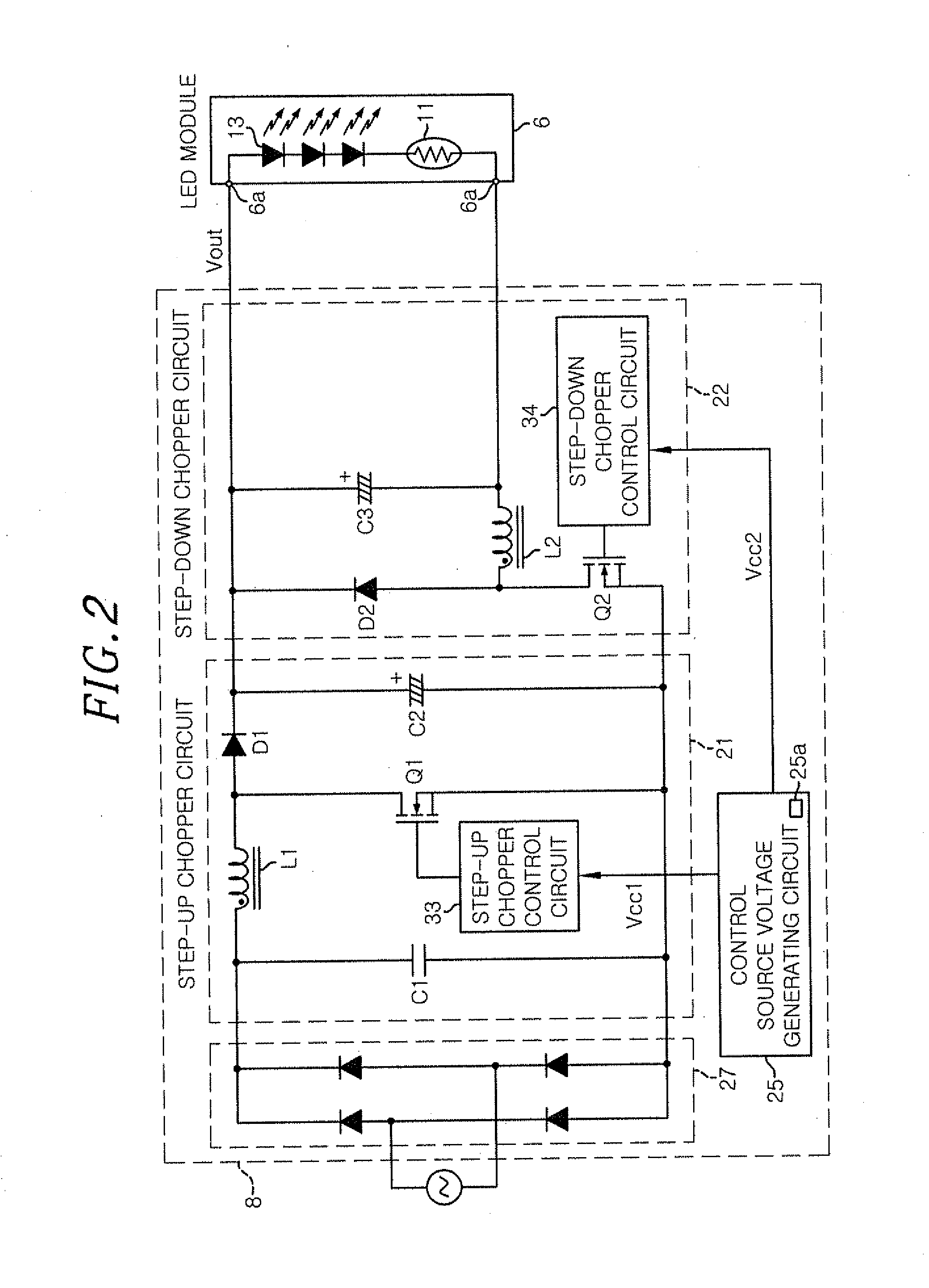
[0053]In the second embodiment, the LED module 6 includes a plurality of LEDs 13 connected in series to each other, and a positive temperature coefficient (PTC) thermistor 41 connected in parallel to the LEDs 13.

[0054]The PTC thermistor 41 is an element whose resistance increases by self-heating when a current flows to thereby make it difficult for the current to flow. That is, the PTC thermistor 41 serves as the curren...

third embodiment

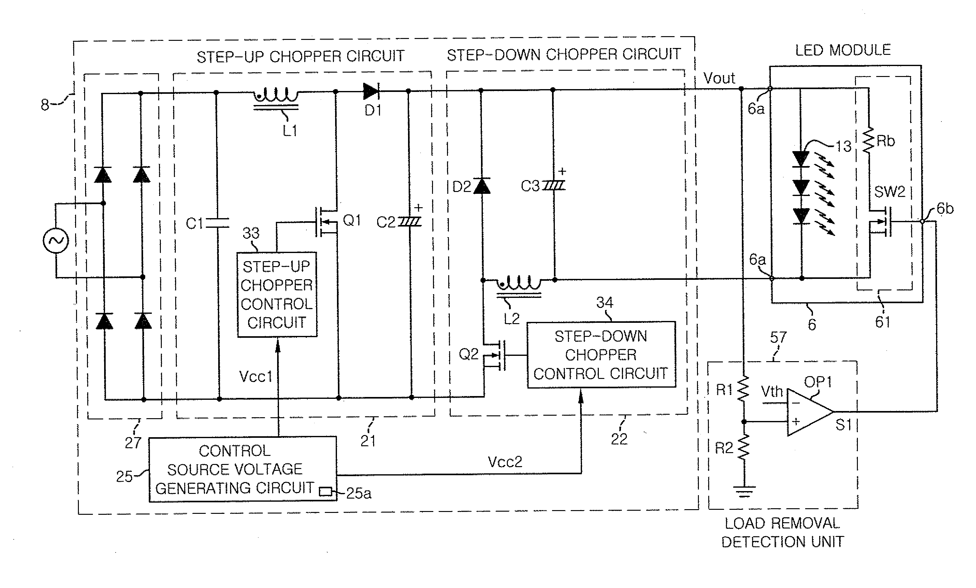
[0062]The cases where the NTC thermistor and the FTC thermistor as the current limiting elements are respectively connected in series and in parallel to LEDs have been described in the first and second embodiments. A case where, instead of the thermistor as a current limiting element, a switch circuit is connected to LEDs will be described in a third embodiment.

[0063]FIG. 4 a circuit diagram illustrating a configuration of an LED illumination apparatus in accordance with the third embodiment of the present invention. The same reference numerals are assigned to the same components as those of the first embodiment, and a description thereof will be omitted.

[0064]The lighting circuit 8 has the same configuration and operation as those of the first embodiment. That is, the step-up chopper circuit 21 is provided at the first stage in the lighting circuit 8 to achieve a high power factor and a wide range of the input voltage. Further, the step-down chopper circuit 22 is provided at the se...


PUM


Abstract

An illumination device includes a light emitting unit; and a lighting circuit, to which the light emitting unit is installed, for supplying an output voltage to the light emitting unit. The light emitting unit includes a light emitting element which is connected to an output terminal of the lighting circuit and emits light by the output voltage supplied from the lighting circuit; and a current limiting unit which limits a current flowing into the light emitting element portion from the lighting circuit at the time when the light emitting unit is installed to the lighting circuit.

Description

FIELD OF THE INVENTION[0001]The present invention relates to an illumination device including a lighting circuit and a light emitting unit.BACKGROUND OF THE INVENTION[0002]Recently, a light emitting diode (LED) has attracted attention as a light emitting element having a long lifespan. In the light emitting diode, it needs to control a forward current of the LED in order to maximize the performance of the LED.[0003]Further, a large amount of current instantaneously flowing when powering, i.e., an inrush current, may not only affect circuit elements other than the LED, but also cause the noise. Accordingly, various measures have been devised in connection with the inrush current.[0004]For example, there has been proposed a method for providing a MOS transistor in series to the LED in order to suppress a dimming noise due to the inrush current in an LED driving circuit which adjusts the luminescent brightness of the LED based on a duty ratio of a PWM signal (see, e.g., Japanese Patent...

Claims


Application Information

Patent Timeline
Patent Type & Authority Applications(United States)
IPC IPC(8): H05B37/02H05B44/00
CPCH05B33/089H05B33/0821H05B45/40H05B45/54
Inventor HAYASHI, MIYOMIZUKAWA, HIROMITSU
Owner PANASONIC INTELLECTUAL PROPERTY MANAGEMENT CO LTD
Why Eureka
Try Eureka