Cantilever system and method of use

a cantilever system and cantilever technology, applied in the direction of artificial islands, foundation engineering, construction, etc., can solve the problems of increasing the cost reducing the service life so as to increase the maximum load, increase the longitudinal length of the beam, and increase the load capacity of the cantilever system

Active Publication Date: 2012-09-06
ENSCO INT INC
View PDF1 Cites 4 Cited by
  • Summary
  • Abstract
  • Description
  • Claims
  • Application Information

AI Technical Summary

Benefits of technology

[0008]In one embodiment, a cantilever system for a rig comprises a hull and a beam movably coupled to the hull. A first end of the beam is extendable over an edge of the hull while a second end of the beam is positioned on the hull. An extension member is coupled to the second end of the beam such that the extension member increases the longitudinal length of the beam. A hold-down member is spaced apart from a support member to increase a maximum load that the beam supports without reducing a maximum reach of the beam from the edge of the hull, wherein the hold-down member is configured to apply a reactive force to the extension member in a direction toward the hull when the first end of the beam is extended over the edge of the hull.
[0009]In one embodiment, a method of increasing a load capacity of a cantilever system that is supported by a hull of a rig comprises extending a portion of a beam of the cantilever system over an edge of the hull and coupling an extension member to an end of the beam while the portion of the beam is extended over the edge of the hull. The method further comprises applying a reactive force to the extension member in a direction toward the hull using a hold-down member when the portion of the beam is extended over the edge of the hull, such that the hold-down member is coupled to the extension member. The method further comprises increasing a spacing between the hold-down member and a support member to increase a maximum load that the beam supports without reducing a maximum reach of the beam from the edge of the hull.
[0010]In one embodiment, a method of increasing a load capacity of a cantilever system that is supported by a hull of a rig comprises providing a beam that is movably coupled to the hull such that a portion of the beam is extendable over an edge of the hull; providing an extension member for connection to the beam to thereby increase an overall length of the beam, wherein the beam has a maximum reach that it may be extended from the edge of the hull when the extension member is coupled to the beam; providing a hold-down member to secure the beam and the extension member to the hull; providing a support member to support the beam on the hull; and increasing a spacing between the hold-down member and the support member to thereby increase a maximum load that the beam supports when extended to its maximum reach.

Problems solved by technology

Much effort has been expended in the reach of the cantilever system, while maintaining load requirements.
However, stronger materials can significantly add to the cost of the cantilever system, and increasing the size and weight of the cantilever system requires substantial modifications to the hull and legs of the rig that are needed to support the cantilever system.

Method used


Image

  • Cantilever system and method of use
  • Cantilever system and method of use
  • Cantilever system and method of use

Examples


Embodiment Construction

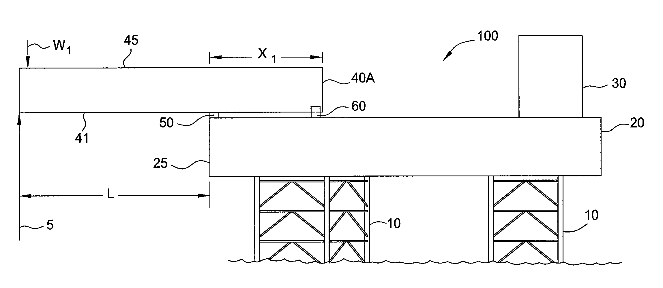
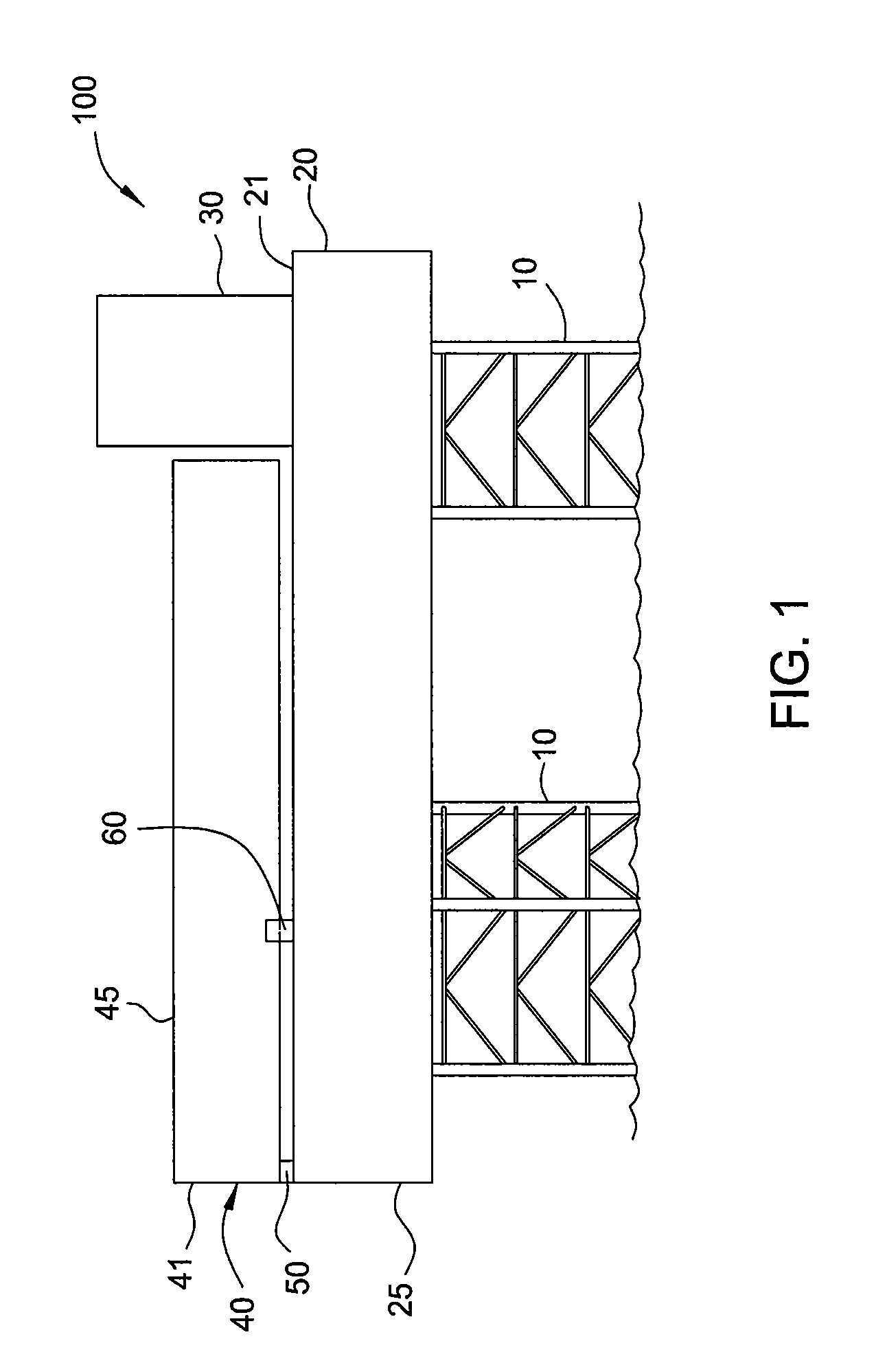
[0019]FIG. 1 illustrates a rig 100 having a cantilever system 40 in a stowed position according to one embodiment. The rig 100 includes a plurality of legs 10, a hull 20, one or more rig structures 30, and a cantilever system 40. The rig 100 may include three or four legs, for example. The hull 20 may include a deck 21 on which the rig structures 30 and the cantilever system 40 are supported. In one embodiment, the rig structures 30 may include equipment, living quarters, and / or a jack-house. The rig structures 30 occupy a portion of the hull deck 21, and may thereby limit or obstruct the length / size of the cantilever system 40 that can be stowed on the hull 20. In operation, the rig 100 is typically transported to an offshore location, the legs 10 are lowered into the sea floor, and the hull 20 is raised to an elevation above the sea surface to secure the rig 100 for performing one or more well operations.

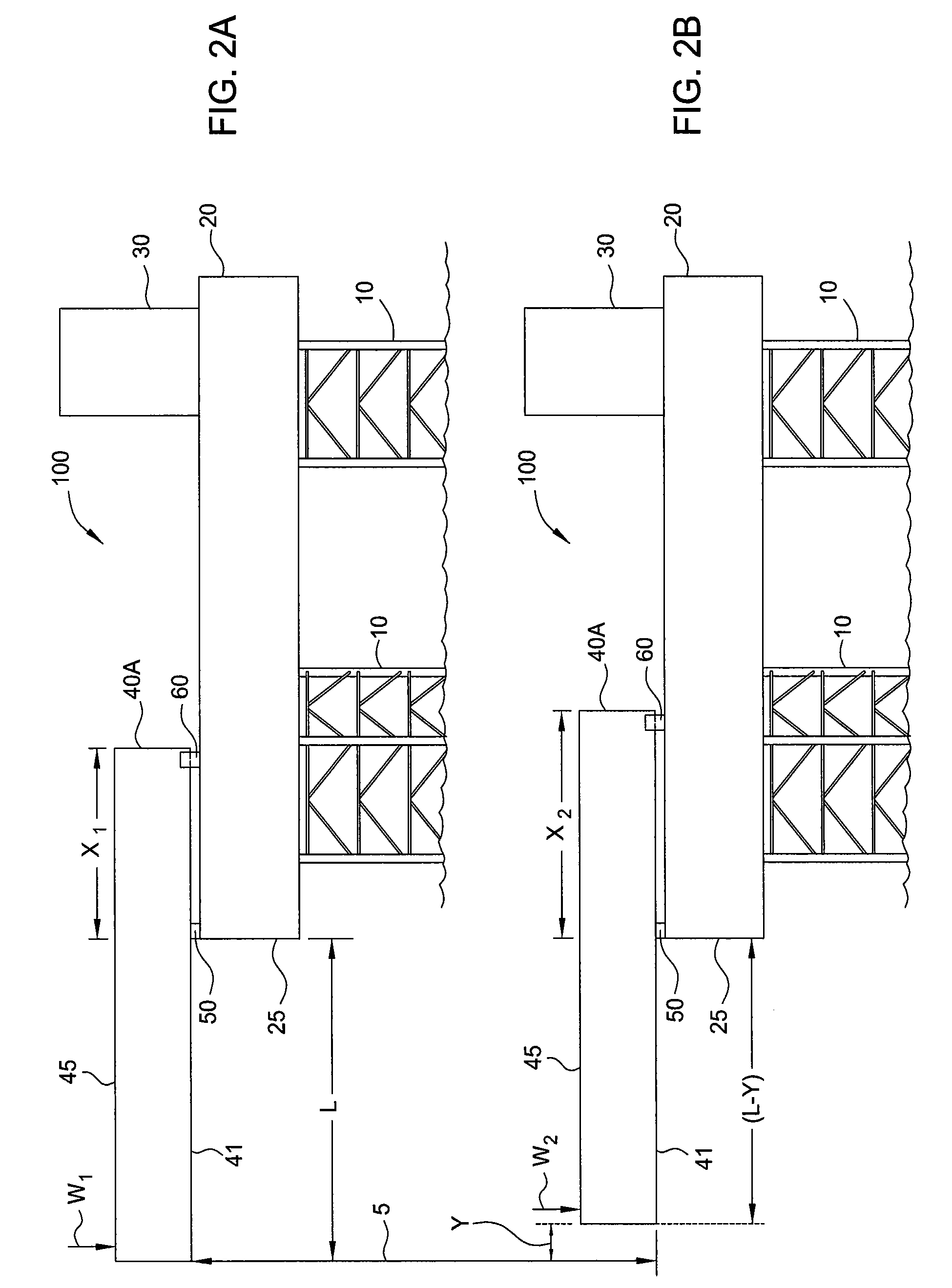
[0020]Beams 41 of the cantilever system 40 are configured to extend and retra...


PUM


Abstract

A cantilever system for a rig comprising a hull, a beam coupled to the hull, an extension member coupled to the beam, and a hold-down member spaced from a support member and coupled to the extension member. A first end of the beam is extendable over an edge of the hull while a second end of the beam is positioned on the hull. The extension member increases the longitudinal length of the beam. The support member is disposed adjacent the edge of the hull. The hold-down member is configured to apply a force to the extension member in a direction toward the hull when the first end of the beam is extended over the edge of the hull. A method of increasing the capacity of the cantilever system comprises increasing the spacing between the support member and the hold-down member.

Description

BACKGROUND OF THE INVENTION[0001]1. Field of the Invention[0002]Embodiments of the invention generally relate to a cantilever system for a jack-up rig. In particular, embodiments of the invention relate to increasing the load-carrying capacity of a cantilever system that is used to support a platform on a jack-up rig.[0003]2. Description of the Related Art[0004]A jack-up rig is an offshore structure that generally includes a hull, a plurality of legs, and a lifting system that is configured to lower the legs into the seabed and elevate the hull to a position capable of withstanding various environmental loads, while providing a stable work deck. So that more wells can be drilled or worked over from the jack-up rig, cantilever systems have been integrated into the hull to extend and retract a drilling platform from the edge of the hull. The greater the distance that the cantilever system can safely extend the drilling platform from the hull, the greater the number of wells that can b...

Claims


Application Information

Patent Timeline
Patent Type & Authority Applications(United States)
IPC IPC(8): E02B17/00
CPCE02B17/00E02B2017/006E02B17/021E21B15/02
Inventor ROPER, RICHARD R.
Owner ENSCO INT INC
Why Eureka
Try Eureka