

Radio base station and connection establishment control method
a technology of connection establishment and control method, which is applied in the direction of connection management, wireless communication, network traffic/resource management, etc., can solve the problem that x2 connections may also be established, and achieve the effect of reducing the number of x2 connections
- Summary
- Abstract
- Description
- Claims
- Application Information
AI Technical Summary
Benefits of technology
Problems solved by technology
Method used
Image

Examples
Embodiment Construction
[0031]Next, embodiments of the present invention will be described with reference to the drawings. Specifically, descriptions will be given of (1) Schematic Configuration of Radio Communication System, (2) Configuration of LTE Base Station, (3) Operations of LTE Base Station, (4) Operation and Effects, and (5) Other Embodiments. Note that throughout the description of the drawings of the following embodiment, identical or similar portions are designated by identical or similar reference numerals.
(1) Schematic Configuration of Radio Communication System
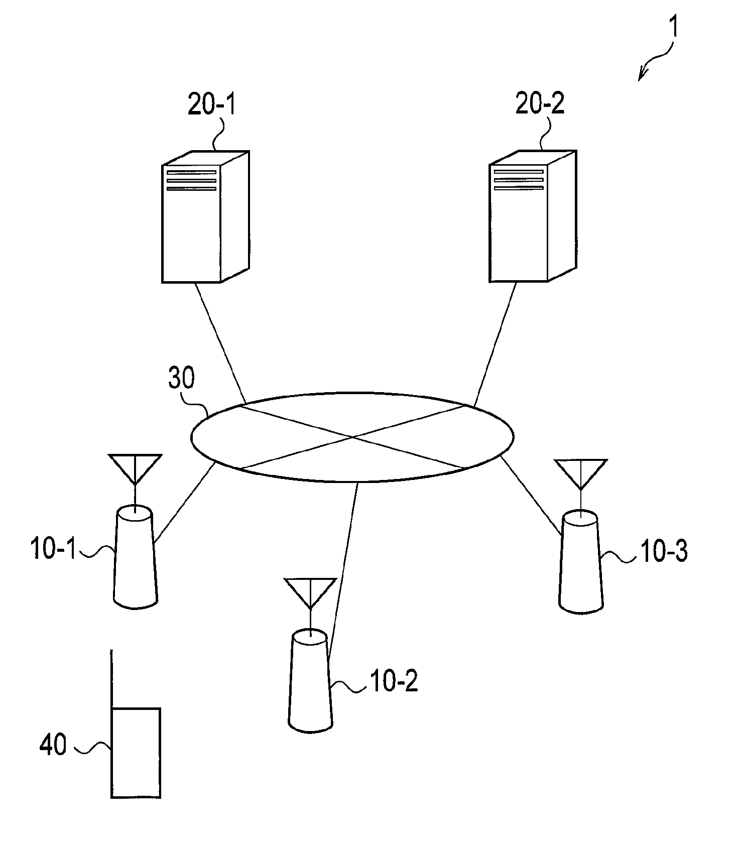
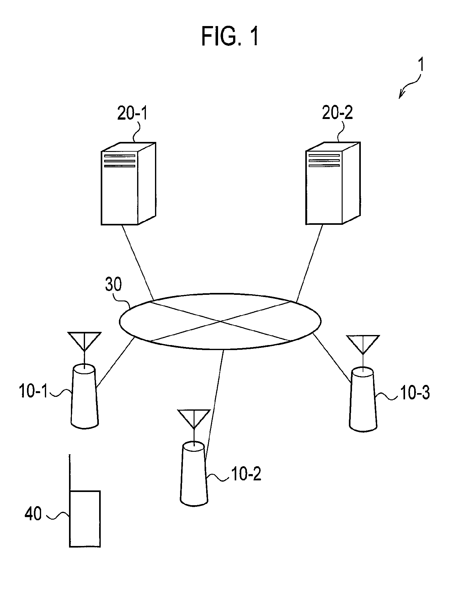
[0032]FIG. 1 is a schematic configuration diagram of a radio communication system of this embodiment. In this embodiment, a radio communication system 1 is constructed by use of LTE techniques. The radio communication system 1 shown in FIG. 1 includes radio base stations (LTE base stations) 10-1, 10-2, and 10-3, MME (Mobile Management Entity) / SGW (Serving Gateway) units 20-1 and 20-2 which are forwarding control devices installed in a ...
PUM
 Abstract
Description
Claims
Application Information