Single-Phase Optical Current Transformer

Active Publication Date: 2012-10-18
HITACHI LTD
View PDF9 Cites 0 Cited by
  • Summary
  • Abstract
  • Description
  • Claims
  • Application Information

AI Technical Summary

Benefits of technology

[0016]Since the single-phase optical current transformer by the present invention uses optical fibers of prescribed dimensions as the Faraday-effect elements, the length of the first and the second optical paths can be made shorter. Therefore, saturation in the size of Faraday rotation angle of the linearly polarized light hardly occurs. This feature offers such an advantageous effect that a large current that may flow on fault for example can be reliably measured. In addition, the influence on the measuring accuracy attributable to temperature variation can be reduced, because the measurement is performed over a smaller area of magnetic field by detecting the Faraday rotation angle of the linearly polarized light propagating through the first and the second optical paths formed by the optical fibers of short length. Moreover, it is practicable to downsize a single-phase optical current tr

Problems solved by technology

However, the wound-type current transformer is large in size and heavy in weight.
The optical current transformer of which optical path is fabricated using block-shaped lead glass is hard to manufacture in a smaller size and requires complicate fabrication process.
On the other hand, GISs are becoming high in their voltage rating and, due to that, also becoming large in capacity and size.
As a consequence of this, a problem arises in that the accurate measuring of current that bases on the Faraday rotation angle measured on the detector end becomes impracticable.
Therefore, th

Method used


Image

  • Single-Phase Optical Current Transformer
  • Single-Phase Optical Current Transformer
  • Single-Phase Optical Current Transformer

Examples


embodiment 1

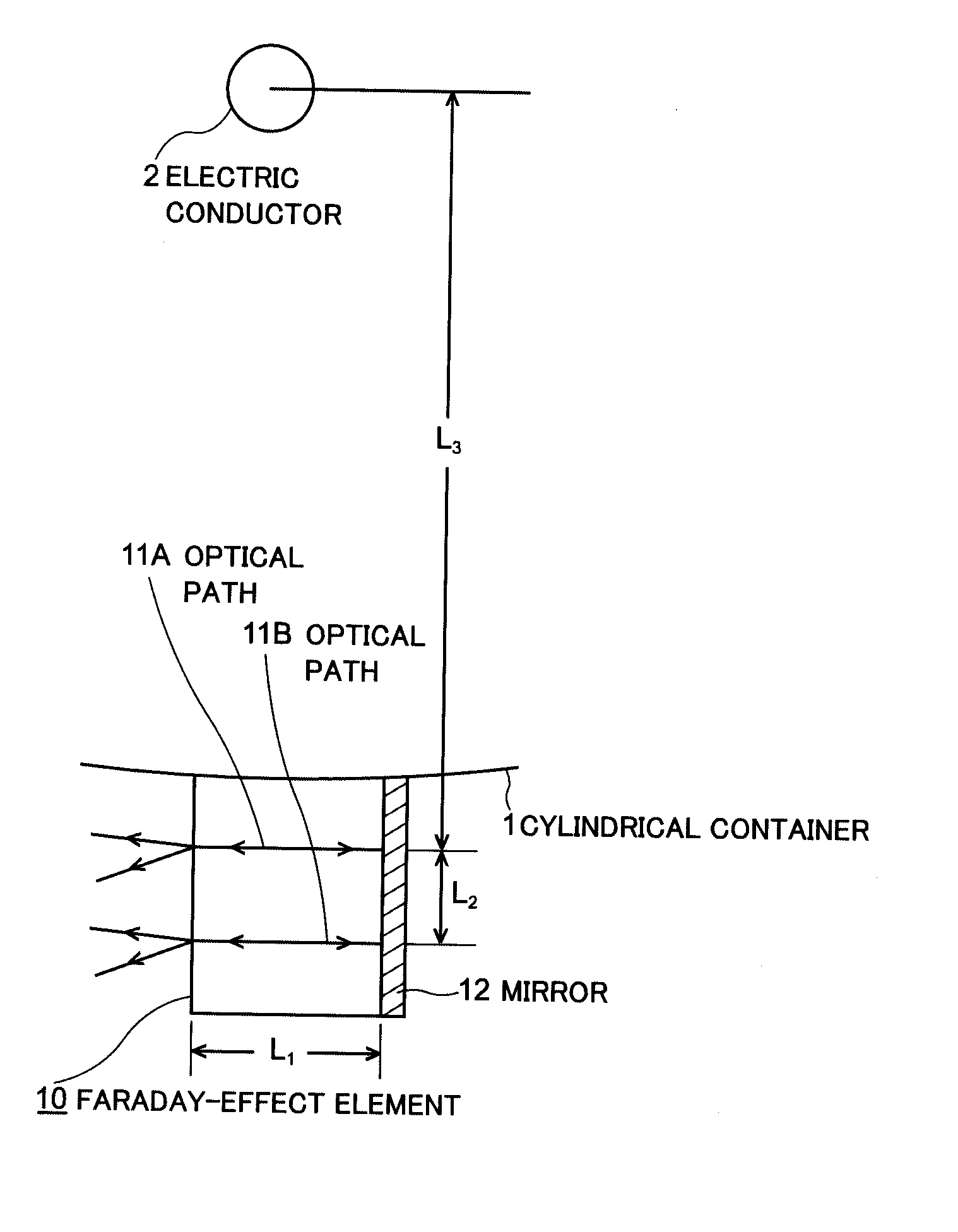
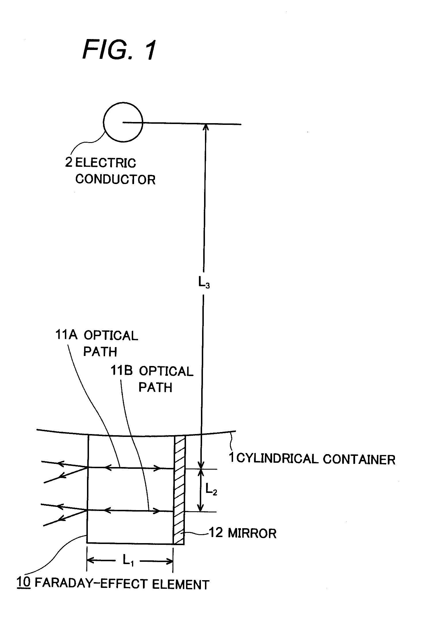
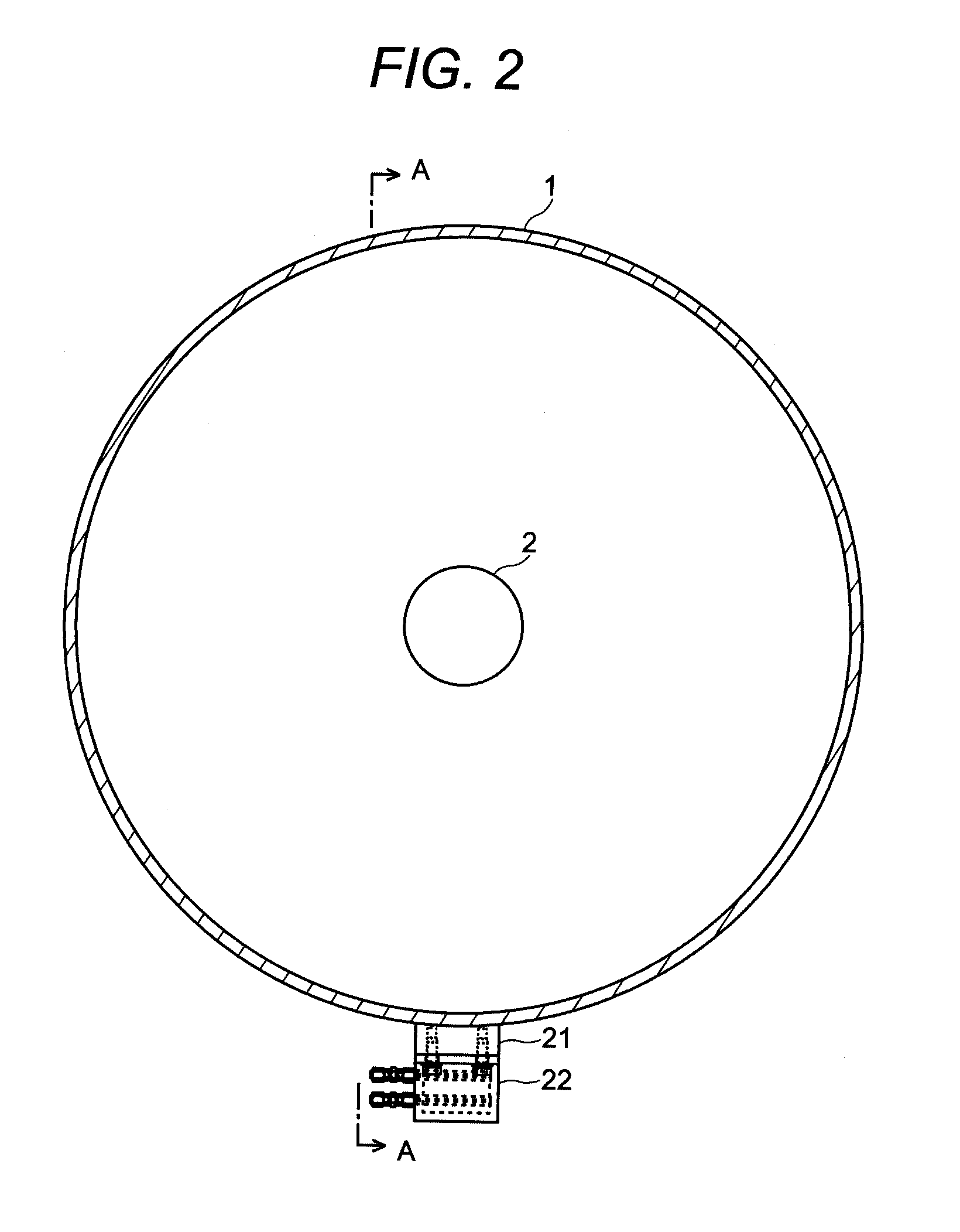
[0036]Details of the single-phase optical current transformer by the present invention will be explained referring to FIGS. 2 to 5 that illustrate an example of an application to GIS or gas insulated buses. The cylindrical container 1, inside which the electric conductor 2 is accommodated, maintains electrical insulation by insulation gas filled therein.

[0037]An installation base 21 is secured on the part of the outer peripheral surface of the cylindrical container 1 with welding, or with other suitable method, namely on the undersurface of the cylindrical container 1 with less subject to direct sunlight in this example as illustrated in FIG. 2 and FIG. 3. The manner of attaching is such that, when viewed in the cross-sectional direction, the seat of the installation base 21 is intersect with the axial direction of the electric conductor 2 through which current flows. A case 22 in which the Faraday-effect element 10 is to be stored is detachably secured on the seat of the installati...


PUM


Abstract

An installation base is secured to part of outer peripheral surface of cylindrical container 1 which has electric conductor 2 arranged thereinside, and a case which stores a Faraday-effect element is detachably secured to the installation base. Faraday-effect element 10 having two optical fibers 24A, 24B of prescribed dimensions, to provide first and second optical paths 11A, 11B maintained in parallel with a predetermined interval therebetween and placed so as to intersect axial direction of electric conductor 2, and having mirror 12 which reflects linearly polarized light at one end surface of each optical fiber. Linearly polarized light from the same light source injected into each of the optical paths 11A, 11B, and current flowing in electric conductor 2 is measured base on the Faraday rotation angle of the linearly polarized light reflected and returned from mirror 12.

Description

TECHNICAL FIELD [0001]The present invention relates to a single-phase optical current transformer particularly to such a single-phase optical current transformer as is capable of measuring reliably single-phase large currents.BACKGROUND ART [0002]To measure current flowing through an electric conductor of high-voltage in a gas insulated switch gear (hereinafter referred to as GIS) or similar apparatus, a wound-type current transformer has been conventionally used. The transformer of such type is a through-type current transformer comprised of an endless core and a secondary winding through which the electric conductor passes. However, the wound-type current transformer is large in size and heavy in weight. Because of this, consideration has been made about application of an optical current transformer that uses the Faraday effect, which is a rotation phenomenon of polarization plane of a light due to an effection of magnetic field. Such optical current transformer is suitable part...

Claims


Application Information

Patent Timeline
IPC IPC(8): G01R31/00
CPCG01R15/246G01R15/24G01R31/327
Inventor ZHANG, WEIYAMAGUCHI, TATSUSHI
Owner HITACHI LTD
Why Eureka
Try Eureka