Fuel injector communication system

a communication system and fuel injector technology, applied in the direction of braking system, position/direction control, brake action initiation, etc., can solve the problem of providing additional circuitry, and achieve the effect of effective operation

Active Publication Date: 2012-11-08
DELPHI TECH IP LTD
View PDF12 Cites 5 Cited by
  • Summary
  • Abstract
  • Description
  • Claims
  • Application Information

AI Technical Summary

Benefits of technology

[0016]Since individual injectors can be sent individual drive pulse signals, the individual injectors in accordance with the first aspect of the present invention (and therefore the ID chips contained therein) can be addressed by the ECU/drive circuitry. Since the ECU knows which cylinder it is addressing, the ID chips no longer need unique bus addresses. The ID chips may be programmed with unique serial numbers for traceability and may even contain the trim data, but they can all have the same bus address. One particular advantage of the use of an electronic latch means in accordance with embodiments of the present invention is that existing injector drive lines/circuitry can be used to enable and disable communication with the ID chip within the injector...

Problems solved by technology

It is therefore unnecessary to provide ...

Method used


Image

  • Fuel injector communication system
  • Fuel injector communication system
  • Fuel injector communication system

Examples


Embodiment Construction

[0050]In the following description it is noted that like numerals are used to denote like features.

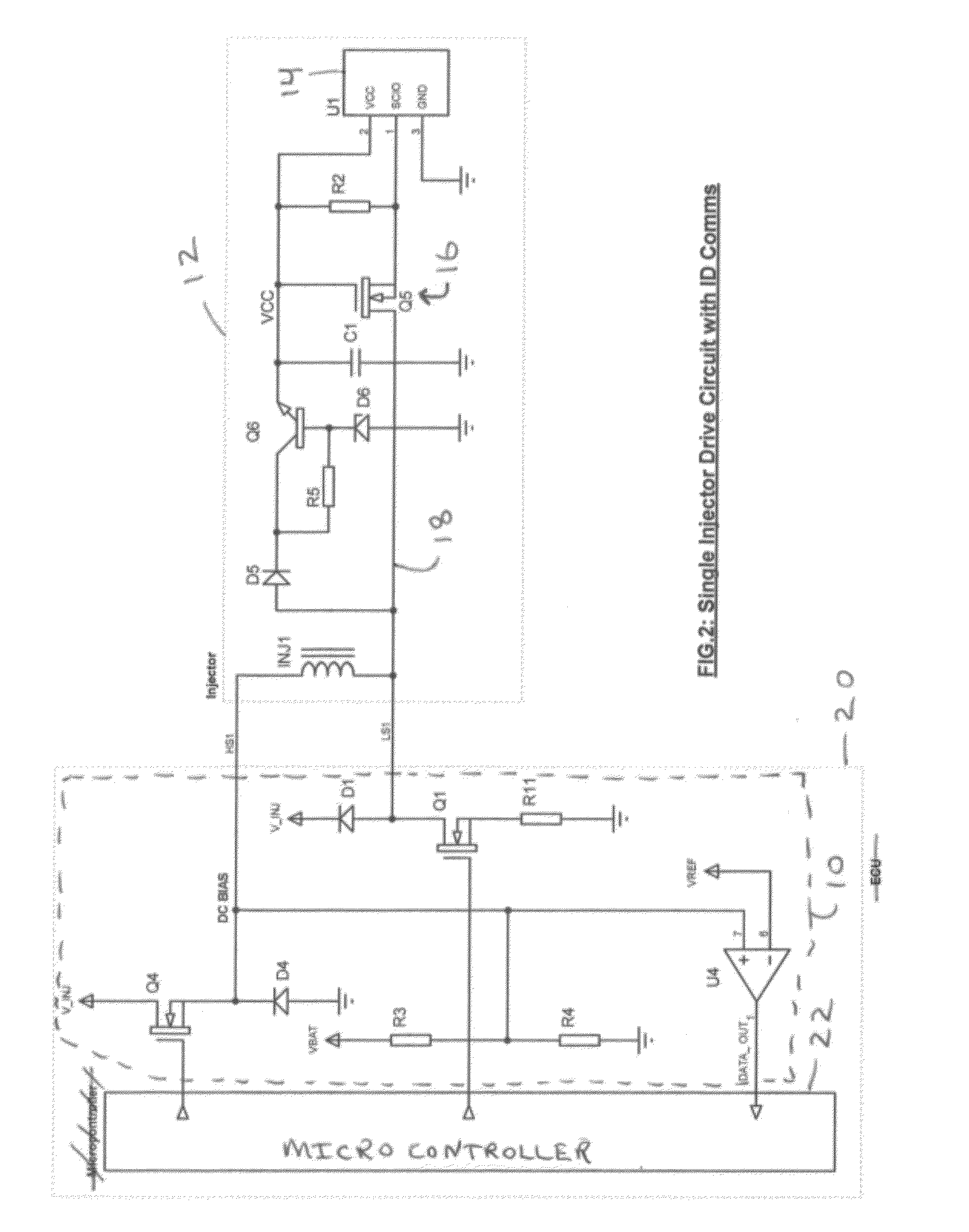
[0051]The present invention provides a mechanism for communicating with an ID chip integrated with an injector using existing drive wires and circuitry and existing diagnostic circuitry. In the embodiments described below a combination of drive pulses and / or rising voltages are used to turn specific “electronic latches” on and off in order to communicate with specific injectors. The “electronic latches” described below can be in one of two states, the first state enabling communication between the ID chip and an injector drive circuit and the second state disabling communication between the ID chip and the injector drive circuit.

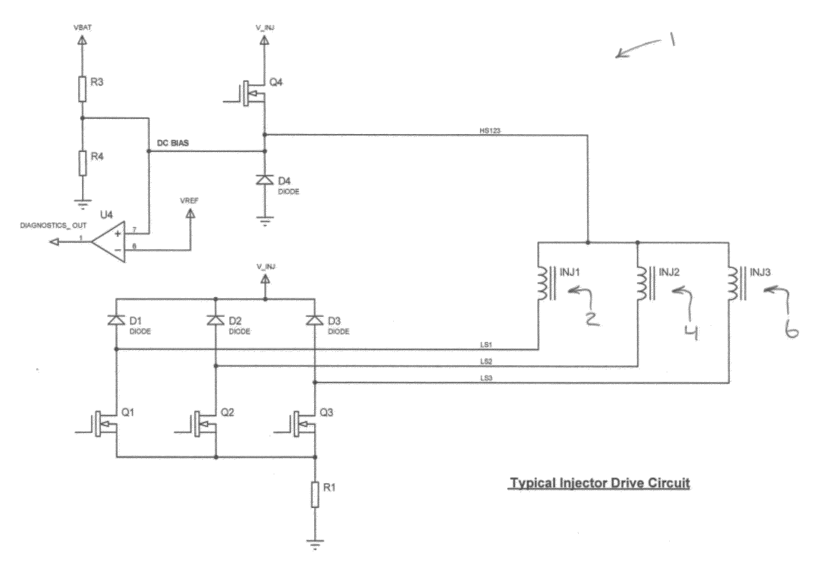
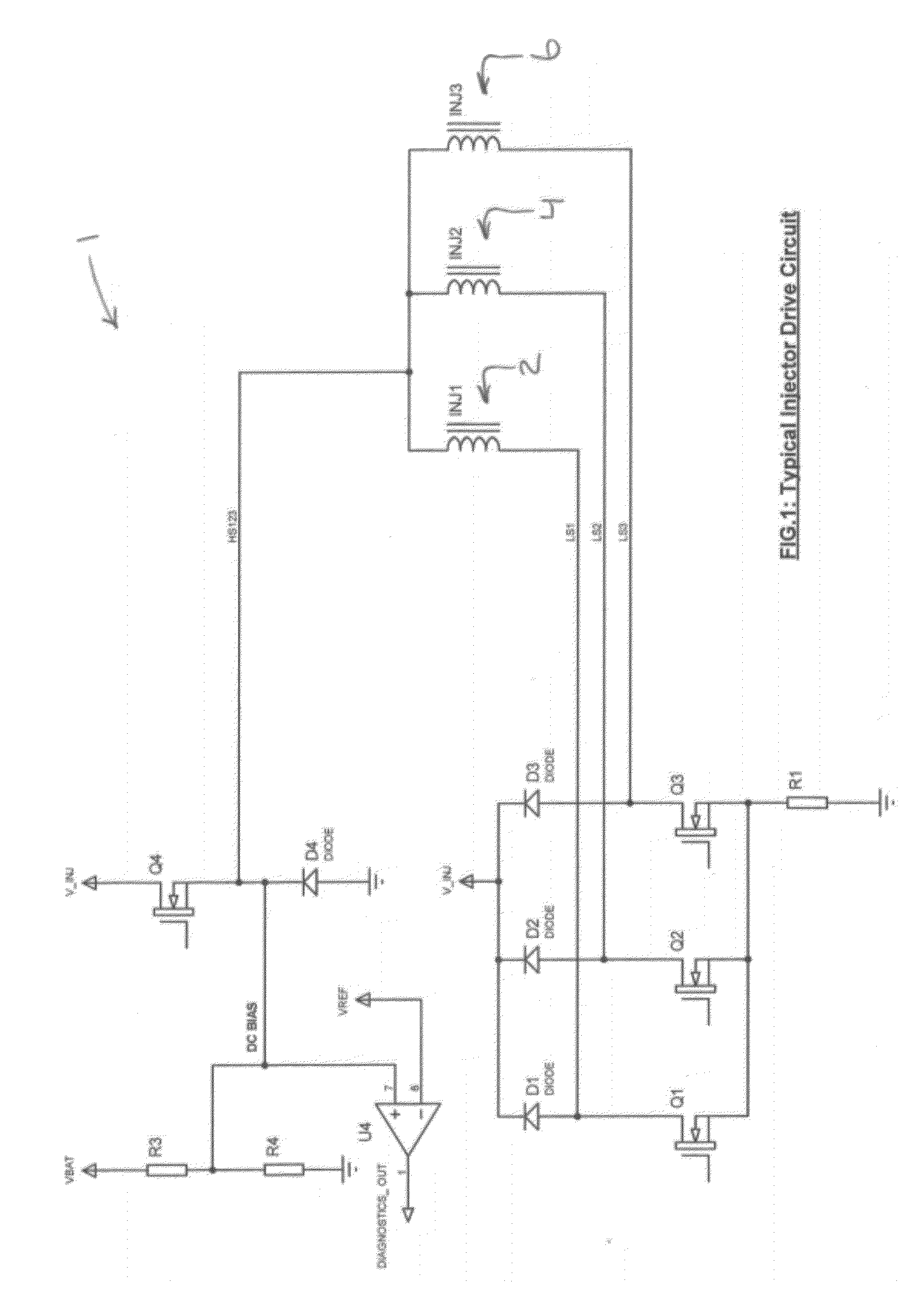
[0052]Turning to FIG. 1, a typical injector drive circuit arrangement 1 is shown in which a bank of three injectors 2, 4, 6 are connected in common with each other. Each injector 2, 4, 6 comprises an injection valve which is operated by means of a solenoid coil...


PUM


Abstract

An injector for a fuel injection system comprising: input means for receiving drive signals from an injector drive circuit for controlling operation of the injector, and an ID chip wherein the injector further comprises an electronic latch means arranged to move between a first state in which the electronic latch means is arranged to be enabled such that the ID chip is in communication with the injector drive circuit via the input means, and a second state in which the electronic latch means is arranged to be disabled such that the ID chip is not in communication with the injector drive circuit via the input means wherein the electronic latch means is arranged to move from the first state to the second state upon receipt at the injector of a drive pulse signal from the injector drive circuit.

Description

CROSS-REFERENCE TO RELATED APPLICATION[0001]This application claims the benefit under 35 U.S.C. §371 of published PCT Patent Application Number PCT / EP 2010 / 068155, filed Nov. 24, 2010, which claims priority to EP patent application number 09176946.3 filed on 24 Nov. 2009, and was published as WO2011 / 064270A1 on Dec. 29, 2011, the entire contents of which is hereby incorporated by reference herein.TECHNICAL FIELD OF INVENTION[0002]The present invention relates to a fuel injector communication system. In particular, the present invention relates to a system and method for communicating with an electronic ID chip that is integrated into an injector within a fuel injection system.BACKGROUND OF INVENTION[0003]During manufacture of a fuel injection system for an engine it is customary to assign trim data to individual injectors to compensate for fueling and timing variations. The trim data (e.g. valve timing offset, nozzle flow offset etc.) is acquired during injector testing and currentl...

Claims


Application Information

Patent Timeline
IPC IPC(8): F02D41/20F02D41/26
CPCF02D41/20F02D41/2435F02D41/2467F02D41/28F02D19/061F02D2041/2051F02M2200/8007F02D41/02F02D41/2432F02D2041/2006H01F2007/1822
Inventor ARCHER, MICHAEL ANTHONYFALLAHI, ABDOLREZA
Owner DELPHI TECH IP LTD
Why Eureka
Try Eureka