Image forming apparatus and image forming method

a technology of image forming apparatus and forming method, which is applied in the direction of electrographic process apparatus, instruments, optics, etc., can solve the problems of difficult to minimize the increase in down-time, the latent image forming position is different, and the toner image is misregistered in the respective color, so as to reduce the relative misregistration of toner images

Active Publication Date: 2012-11-22
RICOH KK
View PDF5 Cites 6 Cited by
  • Summary
  • Abstract
  • Description
  • Claims
  • Application Information

AI Technical Summary

Benefits of technology

[0018]The present invention further describes a novel image forming method. In one example, a novel image forming method forms toner images on respective rotating surfaces of a plurality of image carrying members, and superimposes and transfers the toner images onto a rotating surface of an endless belt member and then onto a recording medium or superimposes and transfers the toner images onto a recording medium carried on the rotating surface of the belt member. The image forming method includes: performing a solid density stabilization process of forming solid tone patterns, each of which includes a plurality of solid toner images different from one another in toner adhesion amount per unit area, on the image carrying members, transferring the solid tone patterns onto the surface of the belt member, detecting toner adhesion amounts per unit area of the solid toner images included in each of the solid tone patterns, and adjusting, on the basis of the result of the detection, an image forming condition to form solid images on the image carrying members with respective target image densities; performing a misregistration reduction process of forming position detection toner images on the image carrying members, transferring the position detection toner images onto the surface of th

Problems solved by technology

In the tandem-type image forming apparatus, owing to, for example, a change in temperature causing a slight change in position of an optical path of an optical system performing optical writing of latent images on the image carrying members, there can arise relative differences in latent image forming position among the four image carrying members for the Y, M, C, and K colors and resultant mis

Method used


Image

  • Image forming apparatus and image forming method
  • Image forming apparatus and image forming method
  • Image forming apparatus and image forming method

Examples


Embodiment Construction

[0030]In describing the embodiments illustrated in the drawings, specific terminology is adopted for the purpose of clarity. However, the disclosure of the present invention is not intended to be limited to the specific terminology so used, and it is to be understood that substitutions for each specific element can include any technical equivalents that operate in a similar manner.

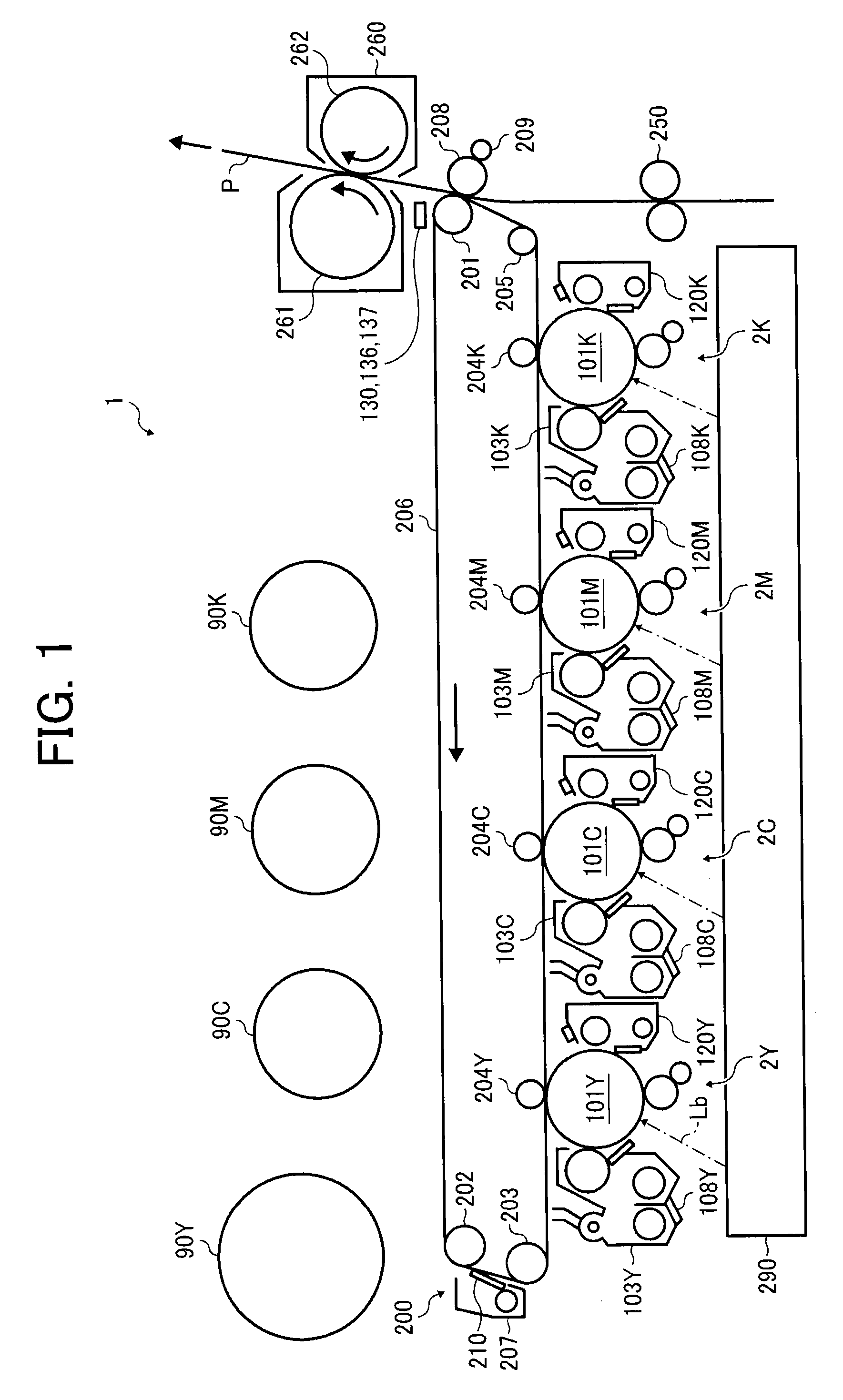
[0031]Referring now to the drawings, wherein like reference numerals designate identical or corresponding parts throughout the several views, an electrophotographic printer 1 will be described as an image forming apparatus according to an embodiment of the present invention. FIG. 1 is a schematic configuration diagram illustrating major components of the printer 1 according to the embodiment.

[0032]The printer 1 includes, in addition to the configurations illustrated in FIG. 1, not-illustrated components, such as a print controller or processor for processing image data transmitted from, for example, a pers...


PUM


Abstract

In an image forming apparatus, a processor performs: a solid density stabilization of adjusting, in accordance with detected toner adhesion amounts of solid toner images of solid tone patterns, a condition to form solid images with respective target image densities; a misregistration reduction of adjusting, in accordance with detection timing of position detection toner images of misregistration detection patterns, a condition to reduce misregistration of toner images; and a halftone density stabilization of adjusting, in accordance with detected toner adhesion amounts of area coverage modulation toner images, a condition to form halftone images with respective target image densities. The processor continuously performs the solid density stabilization and the misregistration reduction, and starts the halftone density stabilization when the solid density stabilization is completed and the misregistration reduction is not completed, to concurrently perform a step of the misregistration reduction and at least a step of the halftone density stabilization.

Description

CROSS-REFERENCE TO RELATED APPLICATION[0001]This patent application is based on and claims priority pursuant to 35 U.S.C. §119 to Japanese Patent Application No. 2011-112719, filed on May 19, 2011, in the Japan Patent Office, the entire disclosure of which is hereby incorporated by reference herein.FIELD OF THE INVENTION[0002]The present invention relates to an image forming apparatus and an image forming method performing a halftone density stabilization process in addition to a solid density stabilization process and a misregistration reduction process.BACKGROUND OF THE INVENTION[0003]There are tandem-type image forming apparatuses, in which toner images of yellow, magenta, cyan, and black (hereinafter referred to as Y, M, C, and K, respectively) colors are formed on image carrying members, e.g., photoconductors and subsequently superimposed and transferred onto either a belt member or a recording sheet on the belt member.[0004]In the tandem-type image forming apparatus, owing to,...

Claims


Application Information

Patent Timeline
IPC IPC(8): G03G15/06
CPCG03G15/0115G03G15/0189G03G15/5054G03G15/0131G03G2215/0132G03G2215/0161G03G2215/0164G03G15/5058H04N1/60H04N1/52
Inventor TANAKA, KAYOKOFUJIMORI, KOHTASONE, KEITA
Owner RICOH KK
Why Eureka
Try Eureka