Valve with connection on the pressure side

Active Publication Date: 2012-11-29
SVM SCHULTZ VERW +1
View PDF12 Cites 7 Cited by
  • Summary
  • Abstract
  • Description
  • Claims
  • Application Information

AI Technical Summary

Benefits of technology

[0034]It is an advantage here, that the medium flow already set in a helical path has this rotational movement still in the area before the second globe valve, and therefore this also presents a clear improvement.
[0035]This modification makes it possible to reshape the medium flow into a helical movement.
[0036]It is here an advantage of this modification, that the channel areas are dimensioned such that the closing element, configured for example as ball, cannot slide or glide in these channel areas. The solution according to the invention achieves also, that the closing element is in the interior of the flow guiding device, and this is in such a way that it cannot glide out of the guiding anymore. The suggestion according to the invention stops the swinging movement of the closing elements or the activation rod, so that this essential disadvantage of the solutions of

Problems solved by technology

At the same time, this is only possible with higher energy input, wh

Method used


Image

  • Valve with connection on the pressure side
  • Valve with connection on the pressure side
  • Valve with connection on the pressure side

Examples


Embodiment Construction

[0048]In the figures identical or corresponding elements each are referred to by the same reference numbers, and therefore are, if not useful, not described anew.

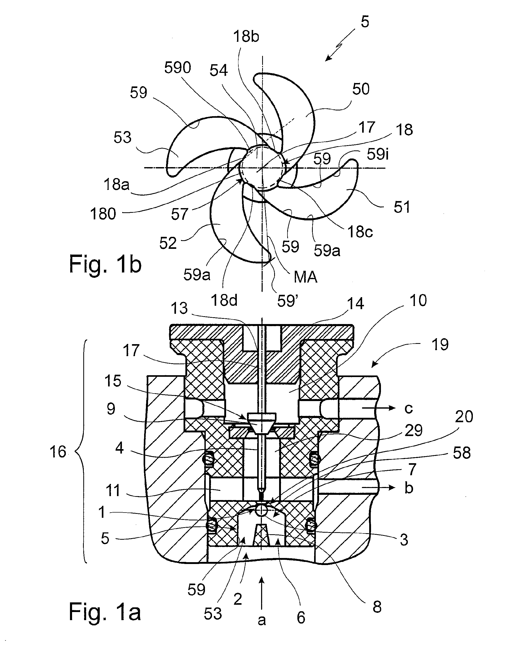
[0049]FIG. 1a shows a section through a valve 19 according to the invention, that is configured, for example, as pressure control valve. The valve 19 according to the invention consists here of a valve body 16, shown essentially in FIG. 1a, and a drive unit configured for example as solenoid that provides the rod drive for the axial (with reference to the center axis 17) movably activation rod 4. Here, the valve body 16 is slid on the yoke-like core piece 14 of the solenoid, the core 14 has a penetration opening 13 serving for receiving or guiding the activation rod 4. The solenoid not shown here is then linked above the core 14 in the usual way of construction. Preferably, the rod drive is designed as solenoid, the armature of the solenoid acting on the activation rod, wherein, for example, a floating support of the activa...


PUM


Abstract

The invention refers to a valve, in particular a pressure valve, comprising a feed area provided in front of a globe valve in flow direction of the medium, wherein the globe valve can be sealed by a loose closing element provided in the feed area, and wherein an activation rod angles the closing element against the flow direction of the medium with reference to the globe valve. The invention is characterized in that in the feed area a flow guiding device is provided, wherein the flow guiding device has several channel areas, so that the medium flowing through the channel areas is set in a helical twist.

Description

BACKGROUND OF THE INVENTION[0001]The invention refers to a valve, comprising a feed area provided in flow direction of the medium in front of a globe valve, wherein the globe valve can be closed by a loose closing element provided in the feed area, wherein an activating rod movable by a rod drive angles the closing element against the flow direction of the medium with reference to the valve seat of the globe valve. Valves of this type are employed in particular as pressure control valves, for example in the hydraulic circuit of an automatic transmission. In the valve an activation rod moveable by a rod drive is provided acting on the loose closing element. For example, a solenoid is employed as rod drive. The solenoid or the rod drive, for example, is activated for operating the closing element for releasing the flow of the medium through the globe valve. Usually, in the switched off or decreased state of the rod drive or the solenoid, respectively, the closing element is pressed on...

Claims


Application Information

Patent Timeline
IPC IPC(8): F16K1/42F16K31/06F16K5/20
CPCF16K1/14F16K47/00F16K31/0637F16K1/42Y10T137/87917
Inventor SCHERER, GEORGMANG, HELMUTSCHREIBER, FLORIAN
Owner SVM SCHULTZ VERW
Why Eureka
Try Eureka