Spring steel high overpressure vent structure

a high-pressure vent and spring steel technology, applied in the direction of functional valve types, transportation and packaging, containers, etc., can solve the problem of a certain degree of backstop deflection, and achieve the effect of lowering the overall heigh

Inactive Publication Date: 2009-12-08
FIKE CORP
View PDF16 Cites 16 Cited by
  • Summary
  • Abstract
  • Description
  • Claims
  • Application Information

AI Technical Summary

Benefits of technology

[0024]Each backstop serves to prevent the pressure relief portion of a respective vent unit from being opened under a predetermined overpressure through an arc that would result in the panel material exceeding the yield strength of the spring steel precluding the pressure relief portion from immediately returning to its initial position substantially closing the vent aperture, after opening of the pressure relief portion.
[0025]An alternate backstop for the rectangular vent apparatus may be of tubular, generally oval configuration having a curved segment presenting a curvilinear outer surface positioned to arrest movement of the relief portion of the vent unit to its selected open position. The curved segment of the tubular backstop has a curvilinear outer surface portion of greater curvature adjacent the relief portion of the stainless steel panel than an adjacent curvilinear outer surface portion of the tubular backstop. The outermost portion of the tubular backstop preferably has a series of openings therein allowing access to connectors that serve to affix the backstop in predetermined disposition with respect to the pressure relief portion of the spring steel panel. The curved surface of the tubular backstop also contributes to absorption and dissipation of kinetic energy during opening of the relief portion of the vent structure.
[0026]Rectangular vent apparatus having a tubular backstop is especially advantageous for use in certain installations, because of its lower overall height in a direction away from the spring steel panel and the ability to use the tubular backstop with a number of different sized panels.

Problems solved by technology

When high overpressure events occur, as for example is the case with a violent explosion, engagement of the relief portion of the vent unit with the backstop may result in deflection of the backstop to a certain degree.

Method used


Image

  • Spring steel high overpressure vent structure
  • Spring steel high overpressure vent structure
  • Spring steel high overpressure vent structure

Examples


Embodiment Construction

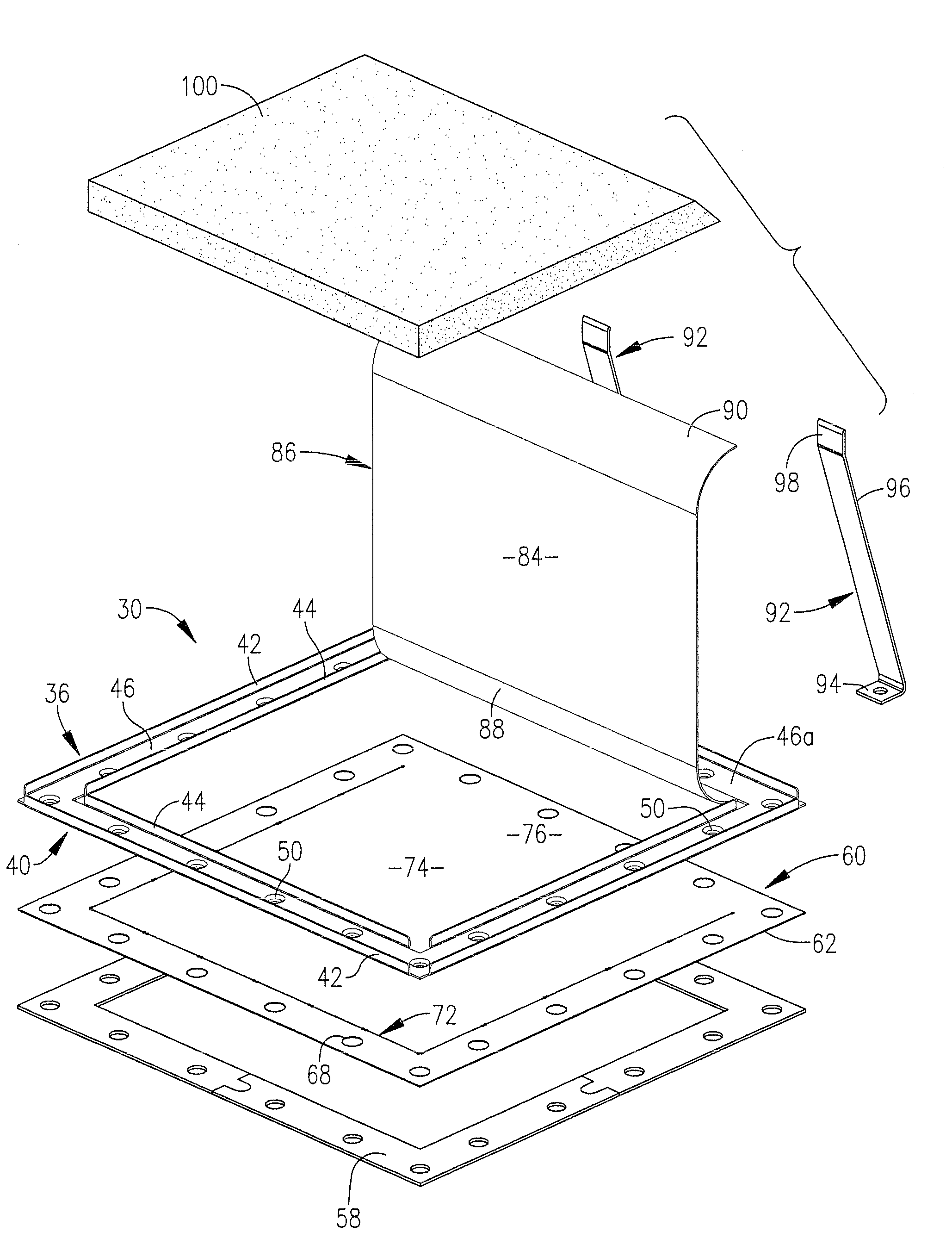
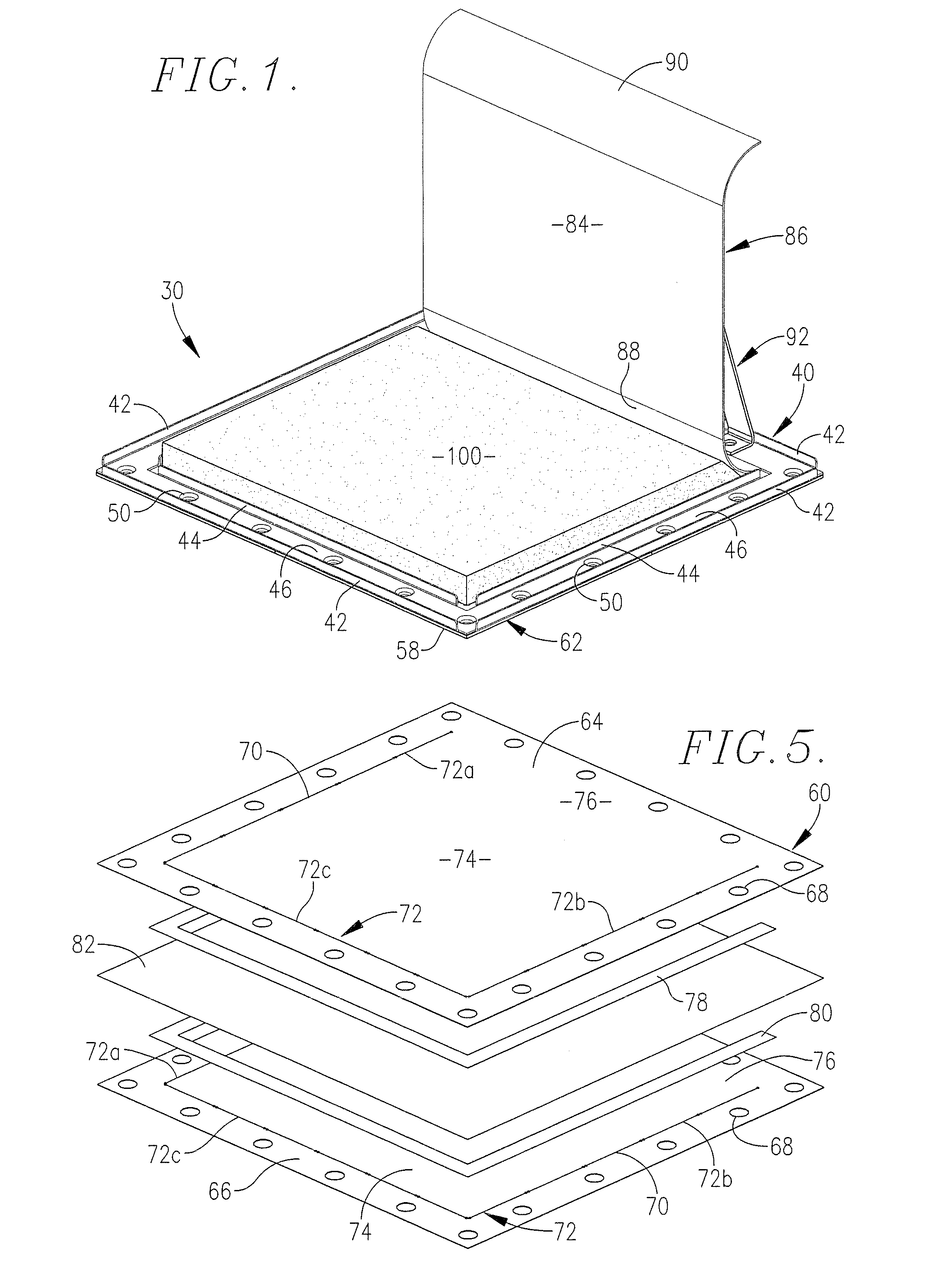
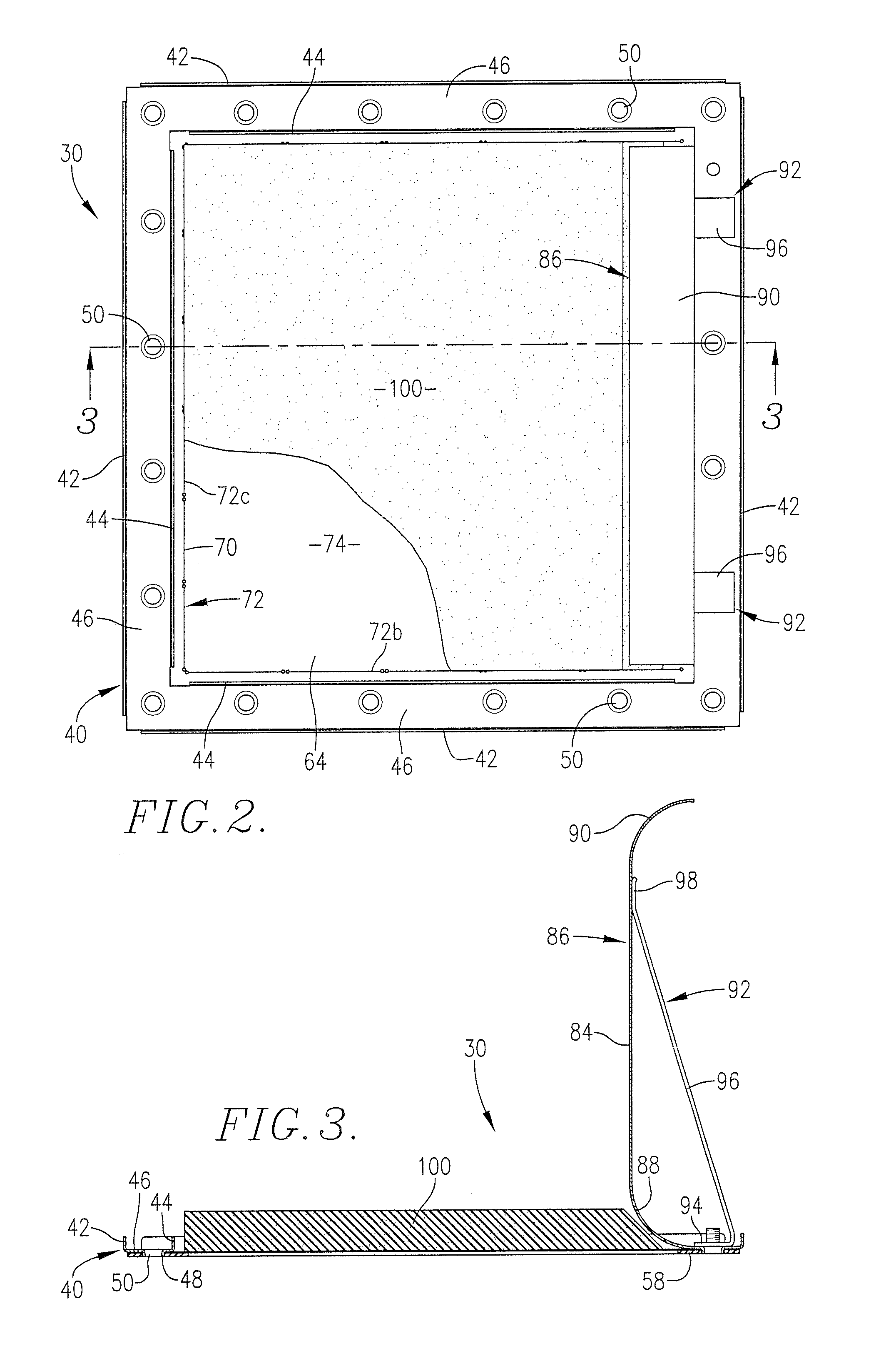
[0054]The preferred rectangular vent apparatus of this invention is illustrated in FIGS. 1-7 and designated generally by the numeral 30. Apparatus 30 is adapted to be mounted in normal closing disposition to the vent aperture 32 of structure 34 (FIG. 6) presenting an area requiring protection from an untoward overpressure event. It is to be understood in this respect that the vent apparatus 30 of this invention may be supplied to a user in the form shown in FIGS. 1-7, or in conjunction with alternate frame supports, as for example shown in FIGS. 15, 17, and 20-22.

[0055]A rectangular metal frame element 36 may, for example, be mounted on and secured to structure 34 in surrounding relationship to vent aperture 32. The internal opening 38 of frame element 36 is generally aligned with the vent aperture 32 in structure 34. A frame unit 40 of vent apparatus 30 is mounted on frame element 36 and the underlying structure 34. Frame unit 40 has four out-turned, lip portions 42 and 44 spaced f...


PUM


Abstract

Rectangular or circular vent apparatus for protecting a confined space having a vent aperture for relief of an overpressure condition is provided with each including vent structure having a vent unit adapted to be positioned over the vent aperture in normal closing relationship thereto. Each vent unit preferably includes at least one spring steel panel, or spring steel leaves positioned against a metal sheet, provided with a movable pressure relief portion having an initial position extending across the vent aperture. A backstop is provided for arresting the degree of movement of the spring steel. The spring steel panel or the spring steel leaves have a sufficient modulus of resilience and elasticity to cause the relief portion of the spring steel panel or the metal sheet to return to their respective initial positions from the open positions thereof upon relief of the overpressure condition in the confined space.

Description

CROSS-REFERENCE TO RELATED APPLICATION[0001]This application is a continuation-in-part of U.S. patent application Ser. No. 11 / 465,257, filed Aug. 17, 2006, entitled SPRING STEEL HIGH OVERPRESSURE VENT STRUCTURE, incorporated by reference herein.BACKGROUND OF THE INVENTION[0002]1. Field of the Invention[0003]The present invention relates to generally rectangular or circular vent apparatus for protecting a confined space having a vent aperture for relief of a high overpressure condition. The vent apparatus is especially useful for covering relief openings in enclosures subject to rapid pressure build-ups such as may occur during explosions or uncontrolled combustion events in bag houses, duct work communicating with the bag houses, processing equipment, duct work leading to and from the processing equipment, buildings, pressure vessels, and other types of commercial and industrial installations where explosions or uncontrolled combustion events producing high overpressures may occur.[...

Claims


Application Information

Patent Timeline
Patent Type & Authority Patents(United States)
IPC IPC(8): F16K17/16E04B1/00
CPCF16K17/162Y10S137/91Y10T137/1714Y10T137/1744F16K17/14F16K13/04B65D90/32
Inventor EIJKELENBERG, TOMJAKUS, GUYDOM, GUIDO
Owner FIKE CORP
Why Eureka
Try Eureka