Light emitting apparatus

Inactive Publication Date: 2012-12-13
GIO OPTOELECTRONICS CORP
View PDF6 Cites 67 Cited by
  • Summary
  • Abstract
  • Description
  • Claims
  • Application Information

AI Technical Summary

Benefits of technology

[0013]In view of the foregoing subject, an objective of the present invention is to provide a light emitting apparatus that can directly replace the conventional fluorescent tube without changing the circuit of the lighting.
[0036]As mentioned above, the light emitting apparatus of the invention is a LED lamp, which does not have the filament of the conventional fluorescent lamp. The light emitting apparatus uses internal elements for simulating the filament, so that the starter and ballast of the conventional fluorescent lamp can still operate with the light emitting apparatus normally. Compared with the conventional art, when the conventional fluorescent lamp is replaced by the light emitting apparatus of the invention, it is possible to prevent the traditional ballast from being burned, or to avoid the procedure of removing the electronic ballast and changing the original circuit. Therefore, as the light emitting apparatus of the invention is installed on the conventional fluorescent lamp base, it can directly replace the conventional fluorescent lamp tube without changing the circuit of the lamp base.

Problems solved by technology

However, when using the light emitting apparatus with LEDs of the same appearance (also called LED lamp) to replace the fluorescent tube 11 cooperating with the conventional ballast, it is hard to confirm that which end of the filament is connected to the power source.
If not, the light emitting apparatus or the electronic ballast may be burned or may not function normally.

Method used


Image

  • Light emitting apparatus
  • Light emitting apparatus
  • Light emitting apparatus

Examples


Embodiment Construction

[0043]The present invention will be apparent from the following detailed description, which proceeds with reference to the accompanying drawings, wherein the same references relate to the same elements.

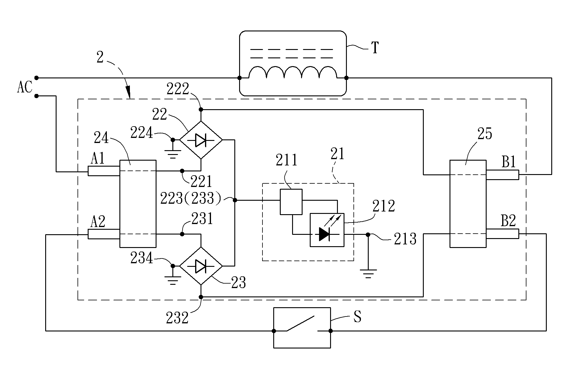
[0044]FIG. 2A is a circuit diagram of a light emitting apparatus 2 according to a preferred embodiment of the invention. To be noted, the light emitting apparatus 2 of the invention is compatible with the conventional fluorescent lamp base with the traditional ballast or electronic ballast, and can be applied to replace the conventional fluorescent tube. Besides, in order to replace the conventional fluorescent tube, the appearance of the light emitting apparatus 2 is fabricated the same as that of the conventional fluorescent tube, so that it can fit the lamp sockets of the conventional lamp base. In order to illustrate the principle of the light emitting apparatus 2, the circuit diagram of FIG. 2A shows the traditional ballast T and starter S of the conventional fluorescent lamp.

[00...


PUM


Abstract

A light emitting apparatus receives an external power and includes a light-emitting unit, two rectifiers, a first electrical connection element and a second electrical connection element. Each of the rectifiers has a first input terminal, a second input terminal, an output terminal and a ground terminal. The output terminals are electrically connected together and are electrically connected with the light-emitting unit. The first electrical connection element is electrically connected with the external power and the first input terminals. The second electrical connection element is electrically connected with the external power and the second input terminals. The light emitting apparatus can replace the traditional fluorescent tube without changing the circuit of the lighting.

Description

CROSS REFERENCE TO RELATED APPLICATIONS[0001]This Non-provisional application claims priority under 35 U.S.C. §119(a) on Patent Application No(s). 100120012 filed in Taiwan, Republic of China on Jun. 8, 2011, the entire contents of which are hereby incorporated by reference.BACKGROUND OF THE INVENTION[0002]1. Field of Invention[0003]The present disclosure relates to a light emitting apparatus and, in particular, to a light emitting apparatus with LEDs.[0004]2. Related Art[0005]FIGS. 1A and 1B are respectively a schematic diagram and a circuit diagram of a conventional fluorescent lamp 1. The fluorescent lamp 1 is a tool for converting electricity into light.[0006]The fluorescent lamp 1 includes a fluorescent tube 11 and a lamp base 12. The fluorescent tube 11 includes two electrical connection elements 111 and a tube 112, and the lamp base 12 includes two lamp sockets 121, a ballast 122, a starter 123, and a base body 124. To be noted, FIG. 1A does not show the ballast 122 and the s...

Claims


Application Information

Patent Timeline
IPC IPC(8): H05B37/00H05B44/00
CPCF21V23/003Y02B20/386H05B33/0809F21K9/17H05B33/0884F21K9/278Y02B20/30H05B45/3578H05B45/40H05B47/26F21K9/27
Inventor LIN, CHUNG-JYHYANG, WU-CHANG
Owner GIO OPTOELECTRONICS CORP
Why Eureka
Try Eureka