

Liquid plunger driven type rubber bag collector for well logging
A current collector and driving technology, which is applied in the directions of measurement, wellbore/well components, earthwork drilling and production, etc., can solve problems such as misalignment of instruments, explosion of rubber balls, blockage of liquid inlet or infusion pipeline, and achieve operation And easy to use, prevent scratches, the effect is remarkable
- Summary
- Abstract
- Description
- Claims
- Application Information
AI Technical Summary
Problems solved by technology
Method used
Image

Examples
Embodiment 1
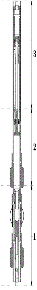
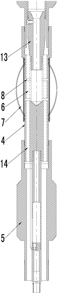
[0019] Embodiment 1: A rubber bladder current collector driven by a self-contained liquid plunger for well logging. This device is mainly divided into three parts and a packaging shell, including the short connection 1 of the bladder current collector and the connection with the short connection 1 of the bladder current collector. The plunger-driven liquid storage chamber short-circuit 2, the motor-driven short-circuit 3 connected to the plunger-driven liquid storage chamber short-circuit 2, and the oil pipes 4 that are all short-circuited in a unified package, and the skin bag current collector short-circuit 1 is connected with The centralizer 5, of course, the centralizer 5 is connected to the well outlet end of the bladder collector short-circuit 1. The centralizer 5, on the one hand, protects the rubber bladder 7 to the greatest extent to prevent the rubber bladder 7 from being scratched; on the other hand, when the device goes down the well, Righting the tubing 4; the blad...
Embodiment 2
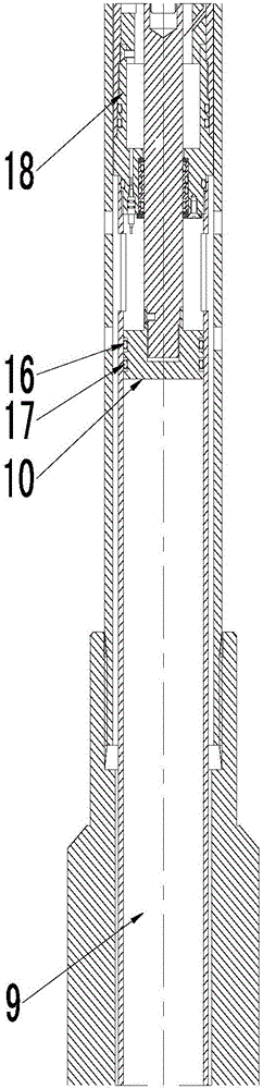
[0020] Embodiment 2: Further, in order to improve the practicability of the device and avoid bursting caused by a large amount of liquid in an instant, an oil-filled short joint 13 is connected between the fluid bypass joint 6 and the liquid storage chamber 9, and the liquid-filled joint The section 13 is connected with the short section 14 of the oil collection.
Embodiment 3
[0021] Embodiment 3: Further, for the embodiment, a further description is made on the fluid bypass joint 6, that is, the fluid bypass joint 6 is provided with a fluid channel 15, and the fluid channel 15 connects the liquid inlet and the flow collector The logging instrument of the previous stage of the flowmeter is short-circuited, thereby improving the high compatibility and applicability of the device.
PUM
 Abstract
Description
Claims
Application Information