Die device and method for manufacturing laminate

A manufacturing method and mold technology, which is applied in manufacturing tools, manufacturing stator/rotor bodies, metal processing equipment, etc., can solve problems such as punching die damage, and achieve the effect of preventing burning

Pending Publication Date: 2021-03-05
MITSUI HIGH TEC INC
View PDF6 Cites 0 Cited by
  • Summary
  • Abstract
  • Description
  • Claims
  • Application Information

AI Technical Summary

Problems solved by technology

When burning occurs in the extrusion ring, i

Method used


Image

  • Die device and method for manufacturing laminate
  • Die device and method for manufacturing laminate
  • Die device and method for manufacturing laminate

Examples


Embodiment Construction

[0031] Hereinafter, embodiments according to the present invention will be described in detail with reference to the drawings. In the description of the drawings, the same reference numerals are assigned to the same elements, and overlapping descriptions are omitted.

[0032] [Stator laminated core]

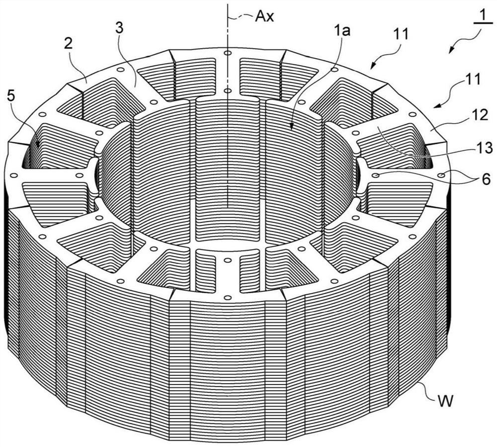
[0033] First, refer to figure 1 , the structure of the stator laminated core 1 will be described. The stator laminated core 1 (stator) has a cylindrical shape. A through-hole 1 a extending along a central axis Ax is provided in a central portion of the stator laminated core 1 . A rotor core (rotor) not shown can be arranged in the through hole 1a. The stator laminated core 1 constitutes a motor together with the rotor laminated core. The stator laminated core 1 has an annular yoke 2 and teeth 3 .

[0034] The yoke 2 has an annular shape and extends to surround the central axis Ax. The inner diameter, outer diameter, and width of the yoke 2 can be set to various sizes accor...


PUM


Abstract

A die device (100) is provided with: a die (232) disposed so as to face a punch (P); and an extrusion ring (233) that is positioned directly below the die (232) and holds the punched member (W) punched by the punch (P) and the die (232). The extrusion ring (233) includes: a through hole (233a) that holds the punching member (W); and an oil supply flow path configured to supply oil into the through-hole (233a) from the inner surface of the through-hole (233a).

Description

technical field [0001] The present invention relates to a mold device and a method for manufacturing a laminate. Background technique [0002] Japanese Unexamined Patent Application Publication No. 2009-297758 discloses a laminated iron core manufacturing apparatus in which an extrusion ring is provided adjacent to a shape punch and a shape punch. Since the inner peripheral surface of the pressing ring is provided in pressure contact with the outer periphery of the punched-out iron core sheets, the iron core sheets that are sequentially pressed in can be brought into close contact with each other. [0003] As mentioned above, burnout may occur due to the pressure acting on the punched part in the extrusion ring. When burning occurs in the squeeze ring, it may cause damage to the punching die or the like. Contents of the invention [0004] The technical problem to be solved by the invention [0005] The present invention provides a mold device and a method for producing ...

Claims


Application Information

Patent Timeline
IPC IPC(8): B21D28/14B21D55/00H02K15/02
CPCB21D28/14B21D55/00H02K15/02
Inventor 岩田谦一郎
Owner MITSUI HIGH TEC INC
Why Eureka
Try Eureka