Variable-volume exhaust system

a variable-volume exhaust system and exhaust system technology, applied in ventilation systems, lighting and heating apparatuses, heating types, etc., can solve the problems of reducing discharge velocity, reducing fan energy consumption, and not realizing fan energy savings

Active Publication Date: 2012-12-20
GREENHECK FAN
View PDF6 Cites 39 Cited by
  • Summary
  • Abstract
  • Description
  • Claims
  • Application Information

AI Technical Summary

Benefits of technology

[0005]The technology described herein includes systems, equipment, and controls that control a variable cross-sectional outlet area nozzle that is used in conjunction with an exhaust fan (upblast, high plume, radial, axial, induced flow, etc.). The system components include, in one embodiment, a variable speed exhaust fan, a...

Problems solved by technology

This method utilizes unconditioned air to maintain constant air volume, however no fan energy savings are realized, as the fan is running at a constant flow rate to maintain constant exhaust fan discharge velocity.
With the desire to reduce fan flow, r...

Method used


Image

  • Variable-volume exhaust system
  • Variable-volume exhaust system
  • Variable-volume exhaust system

Examples


Embodiment Construction

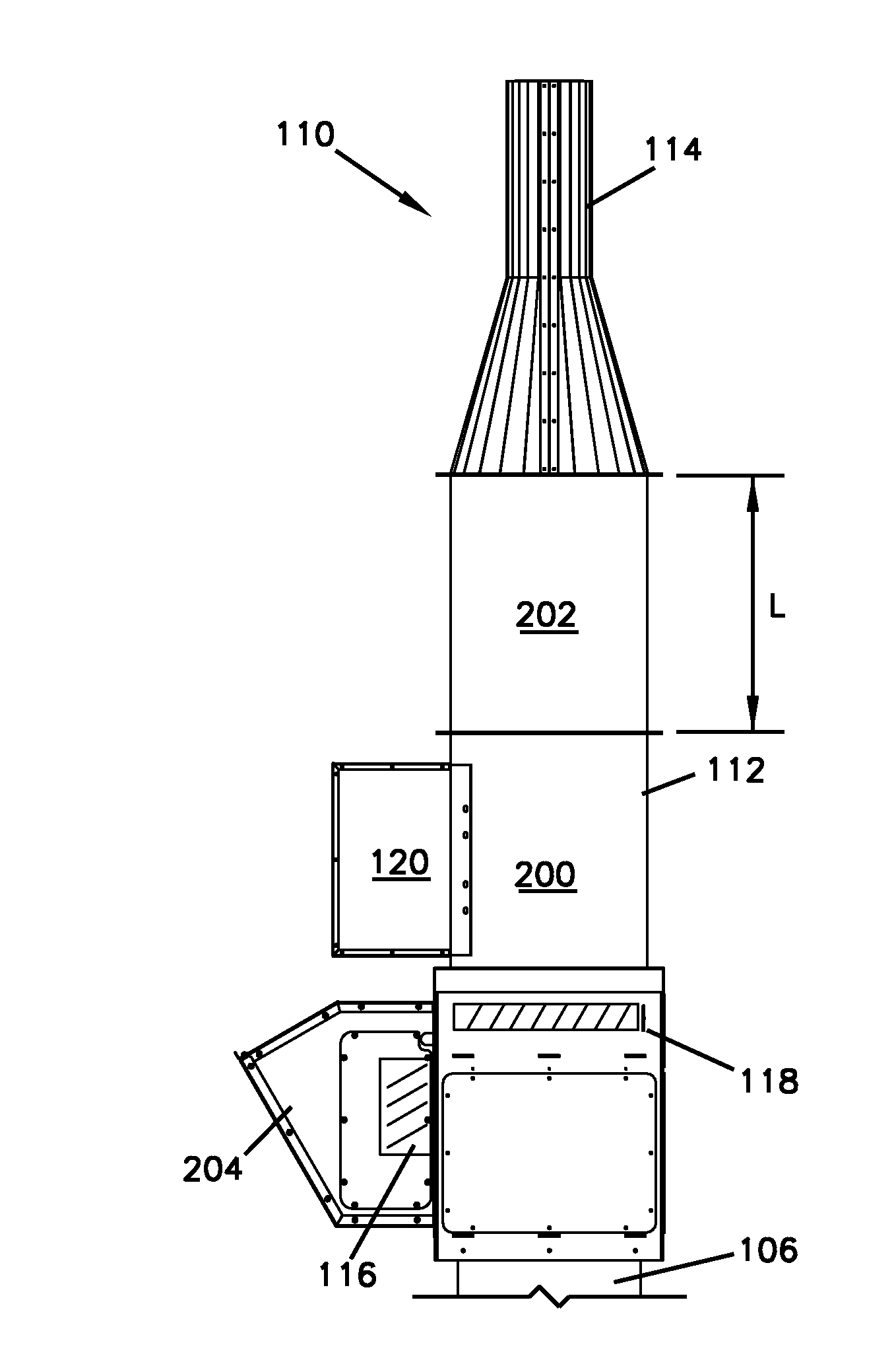
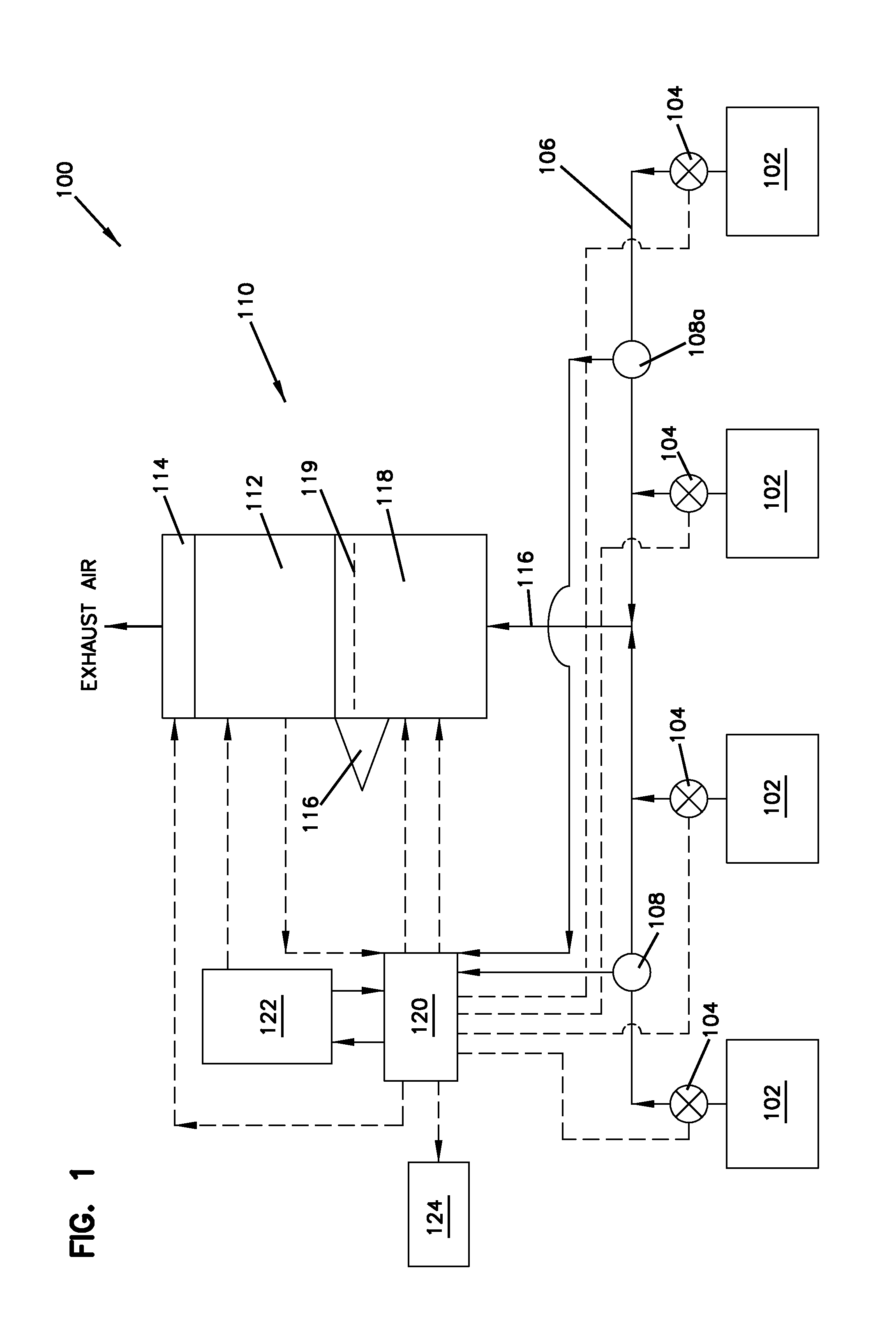
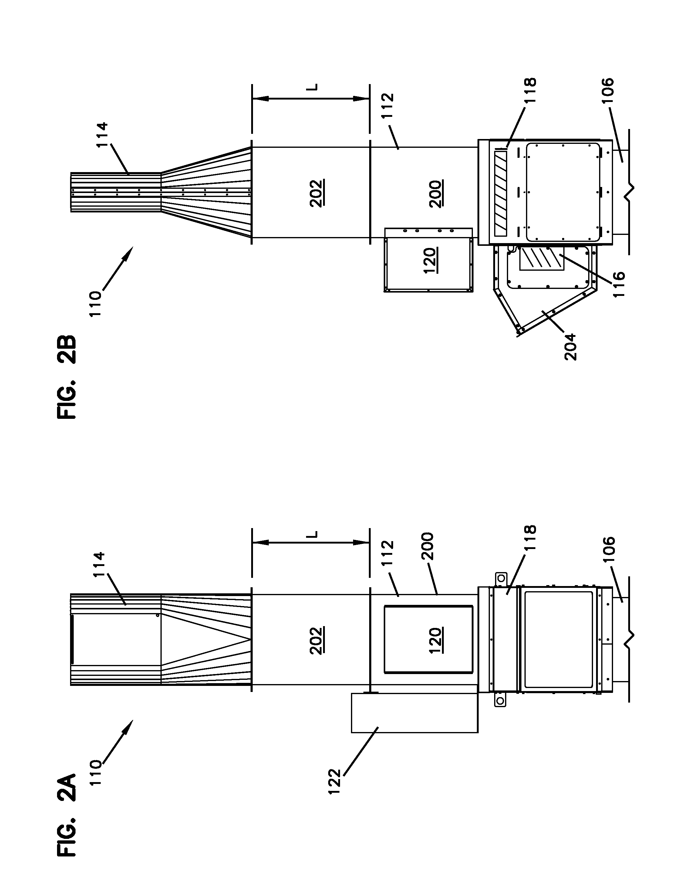
[0030]FIG. 1 depicts a schematic diagram of a variable-volume exhaust system 100. The system 100 exhausts air from one or more spaces 102, typically fume hoods used in laboratory environments, although other spaces are contemplated, as described below. A valve, damper, or other flow-preventing apparatus 104 is located at an outlet of each space 102, thereby selectively preventing flow when desired. Each damper 104 is connected to a duct 106, which may be in a header or other configuration. Located in the duct 106 is at least one static pressure sensor monitor 108. Additional static pressure sensors 108a may be installed elsewhere in the duct 106 for a number of purposes including, but not limited, to redundancy of sensors, averaging of values, or integrity monitoring. The duct 106 is connected to a fan system 110 that includes a fan 112, an outlet nozzle 114 connected to the fan outlet and a bypass damper 116 and bypass air plenum 118. The variable-volume exhaust system 100 is monit...


PUM


Abstract

An exhaust system for exhausting air from a space includes a variable-volume exhaust air moving system having at least one fan having an inlet and an outlet. A duct is connected to the inlet and an outlet nozzle defining a variable cross-sectional outlet area is fluidly connected to the outlet. A selectively operable bypass damper is fluidly connected to the inlet. A sensor is located in the exhaust system for detecting at least one of a pressure condition and a flow condition therein. A control system controls the at least one fan, the outlet nozzle, and the bypass damper, based on a signal sent from the sensor.

Description

CROSS-REFERENCE TO RELATED APPLICATIONS[0001]This application claims priority to and the benefit of U.S. Provisional Patent Application No. 61 / 542,164, filed Oct. 3, 2011, and entitled “Variable-Volume Exhaust System”; U.S. Provisional Patent Application No. 61 / 497,152, filed Jun. 15, 2011, and entitled “Variable-Volume Exhaust System”; U.S. Provisional Patent Application No. 61 / 496,944, filed Jun. 14, 2011, and entitled “Variable-Volume Exhaust System”; and U.S. Provisional Patent Application No. 61 / 496,829, filed Jun. 14, 2011, and entitled “Variable-Volume Exhaust System”; the disclosures of which are hereby incorporated by reference herein in their entireties.INTRODUCTION[0002]Currently, national, state and local codes, as well as specific project requirements, dictate the minimum velocity allowed to be discharged out of an exhaust fan discharge nozzle for a laboratory hood or other (potentially) contaminated or noxious space. For instance, ANSI Z9.5 (American National Standard—...

Claims


Application Information

Patent Timeline
IPC IPC(8): F24F11/04F24F13/10
CPCF23L17/005F24F7/025F04D27/003F04D27/009Y02B30/746F24F11/77B08B15/002F24F2007/001F24F2110/40Y02B30/70B08B15/00F04D29/44
Inventor WENDORSKI, RONALD L.ENZENROTH, JOHNPODJASKI, TONYROTHMEYER, KYLEKNIERIEM, BRUCEROSSI, ANTHONY
Owner GREENHECK FAN
Why Eureka
Try Eureka