Versatile compact air precleaner, air cleaning method and disposable air filter cartridge for air precleaner

a technology of air precleaner and air filter, which is applied in the direction of liquid degasification, separation process, separation separation, etc., can solve the problems of limiting the application of air precleaners, adversely affecting the time and cost of their manufacture, and too big for limited space applications, so as to reduce the cooling thereof, reduce the time and cost of their manufacture, and clean the airflow

Active Publication Date: 2013-01-31
SY KLONE
View PDF3 Cites 32 Cited by
  • Summary
  • Abstract
  • Description
  • Claims
  • Application Information

AI Technical Summary

Benefits of technology

[0013]Drawbacks of the known air precleaners include that they can be too big for limited space applications and they can require custom manufacturing of an individual air precleaner for a particular application due to variations in configuration and performance requirements. This limits the applications of the air precleaners and adversely effects the time and cost for their manufacture. Examples of air precleaner variations between applications which require individual customization include the required direction of ejection of centrifugally separated particulate debris from the precleaner to atmosphere, the orientation of the clean air outlet for providing clean air from the precleaner to the device with which it is used, the size of a filter in the device, the location of the available supporting structure for mounting the air precleaner, and the clean airflow rate required from the precleaner. In the case of powered air precleaners, the life of the motor of the motor-driven fan in the precleaner has been found to be reduced due to debris / dirt buildup on the motor which lowers the cooling thereof. Further, it has been found that the ejection ports for ejecting debris laden air centrifugally separated from the rotating airflow in the air precleaner are subject to being clogged thereby lowering operational efficiency and decreasing filter life.
[0014]There is a need for an improved air precleaner and air cleaning method which overcome these drawbacks and limitations of the known air precleaners. More particularly, there is a need for an improved air precleaner that is compact permitting its use in limited space applications, and is versatile for use in applications with different configurations and clean airflow rate requirements thereby obviating the necessity of a complete custom manufacturing of an individual air precleaner for each application and reducing the time and expense of manufacturing. There is a need for a powered air precleaner which can extend the motor life of a motor driven fan therein. There is also a need for an improved air precleaner and air cleaning method which will facilitate restoring the precleaner to its full operating potential in the event the ejector ports of the precleaner have become clogged.
[0015]The improved versatile compact air precleaner, air cleaning method and disposable air filter cartridge of the present invention address these needs. The versatile compact air precleaner of the invention for separating heavier-than-air particulate debris from debris laden air to provide a clean airflow in accordance with a disclosed embodiment comprises a flow path extending through the precleaner from an inlet to an outlet, a motor-driven fan with a fan blade to draw particulate debris laden air into the inlet and flow the debris laden air along the flow path, and an airflow management structure positioned along the flow path to rotate debris laden air drawn into an inlet about an axis to form a rotating flow that stratifies the debris laden air with the heaviest particles in the outermost orbits of the rotating flow. A separator chamber in the flow path centrifugally separates and removes particulate debris laden air from the rotating flow. At least one ejector port is provided through which particulate debris laden air is ejected from the rotating flow in the separator chamber. The flow path for air passing through the separator chamber is retroflexed en route to the outlet. The precleaner of the disclosed embodiment is elongated in the direction of the axis with the inlet and the at least one ejector port located at opposite ends and the outlet located intermediate the ends. By retroflexing the flow path in this manner the air precleaner is more compact permitting use in applications with limited space.
[0016]Connection of the air precleaner to a supporting structure / device is facilitated by the provision of at least one mount on the precleaner for mounting the precleaner on the support / device. Versatility is improved for using the device in various configurations in that the air precleaner has means for independently adjusting a radial position of each of the outlet, the at least one ejector port and the at least one mount about the axis of the precleaner to configure the precleaner for mounting on the device and connection to the inlet thereof. In the disclosed embodiment, the means for independently adjusting a radial position includes a housing having a plurality of housing sections arranged sequentially along the axis of the air precleaner and means for releasably connecting and adjustably rotating the sections with respect to one another about the axis. The inlet is located on a housing section apart from that of the at least one ejector port and the outlet and is releasably connected to the precleaner. Accordingly, the inlet configuration can be readily changed permitting adaptation of the air precleaner for ingress of air directly from the atmosphere or indirectly from an air supply conduit connected to the inlet. The adjustability afforded by these features allows the use of a single air precleaner in many different applications / configurations and also facilitates, with only minimal changes, the use of different sizes of filters within the air precleaner and changeover of the air precleaner to meet different airflow rate requirements.
[0017]The disclosed, preferred embodiment of the air precleaner of the invention comprises a motor-driven fan with a fan blade mounted on an output shaft of a motor. The fan blade is located in the flow path upstream of the separator chamber and draws particulate debris laden air into the inlet and flows the debris laden air along the flow path. The motor-driven fan is supported on a shroud of the airflow management structure. The shroud tapers outwardly with respect to the axis downstream of the fan blade and shields the motor of the motor-driven fan from the incoming air. A plurality of stationary vanes of the airflow management structure rotate the incoming debris laden air about the axis, compressing the volume of debris laden air to increase the air velocity and centrifugal force acting on the airborne particles. The motor of the motor-driven fan beneath the shroud is in the flow path downstream of the separator chamber, which advantageously reduces dirt and debris buildup on the motor for improved cooling and longer motor life.

Problems solved by technology

Drawbacks of the known air precleaners include that they can be too big for limited space applications and they can require custom manufacturing of an individual air precleaner for a particular application due to variations in configuration and performance requirements.
This limits the applications of the air precleaners and adversely effects the time and cost for their manufacture.
Further, it has been found that the ejection ports for ejecting debris laden air centrifugally separated from the rotating airflow in the air precleaner are subject to being clogged thereby lowering operational efficiency and decreasing filter life.

Method used


Image

  • Versatile compact air precleaner, air cleaning method and disposable air filter cartridge for air precleaner
  • Versatile compact air precleaner, air cleaning method and disposable air filter cartridge for air precleaner
  • Versatile compact air precleaner, air cleaning method and disposable air filter cartridge for air precleaner

Examples


Embodiment Construction

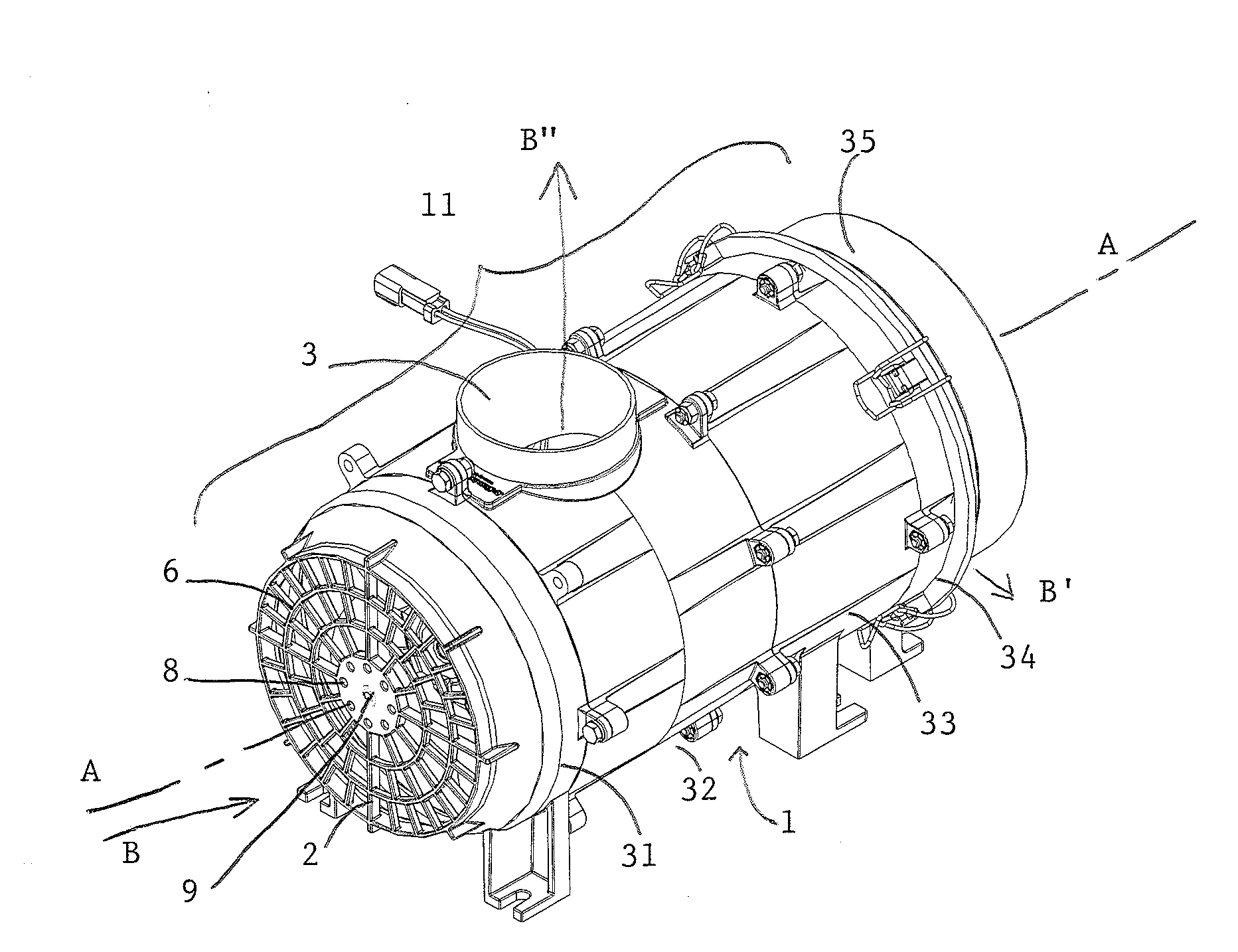
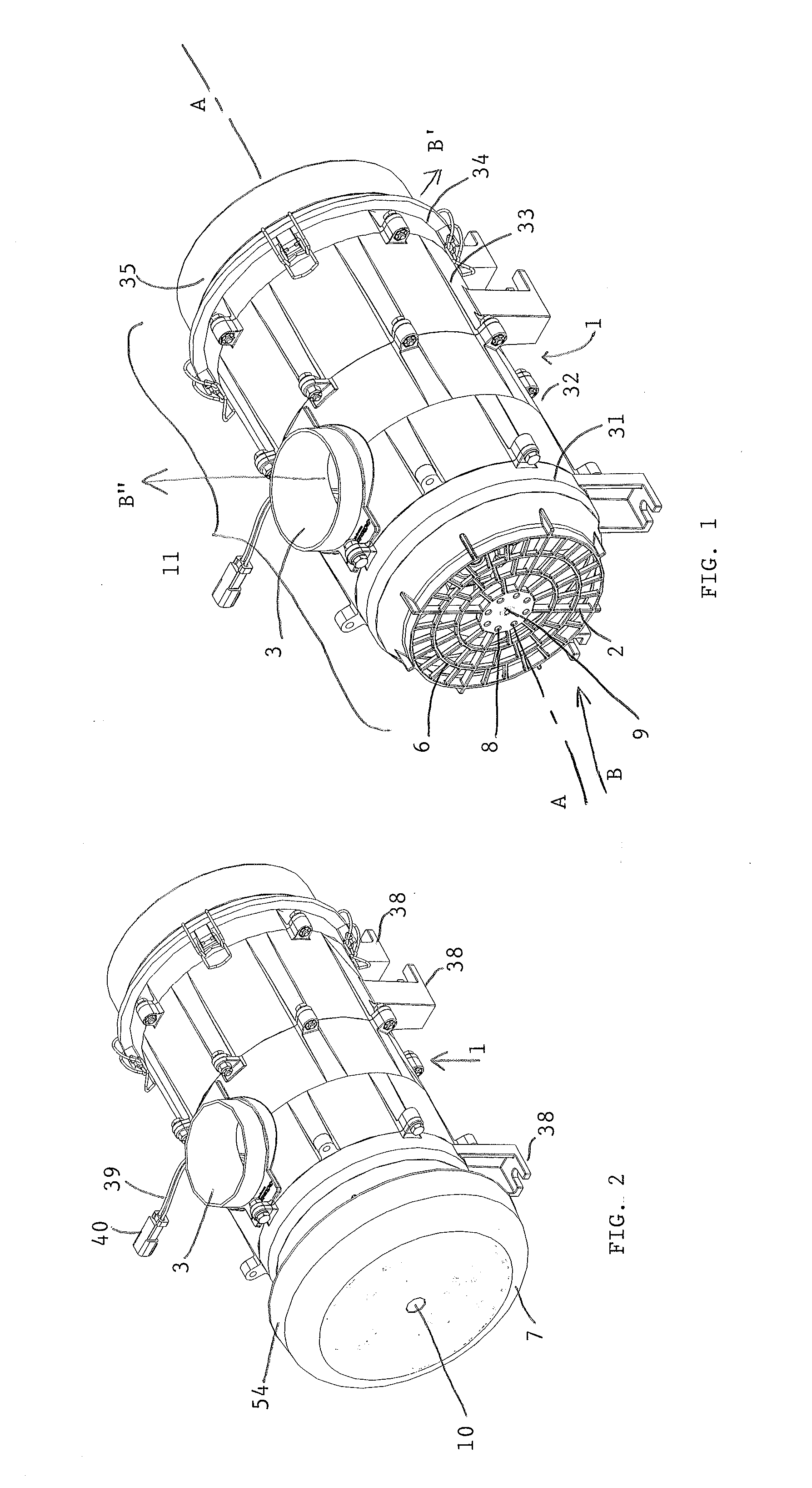
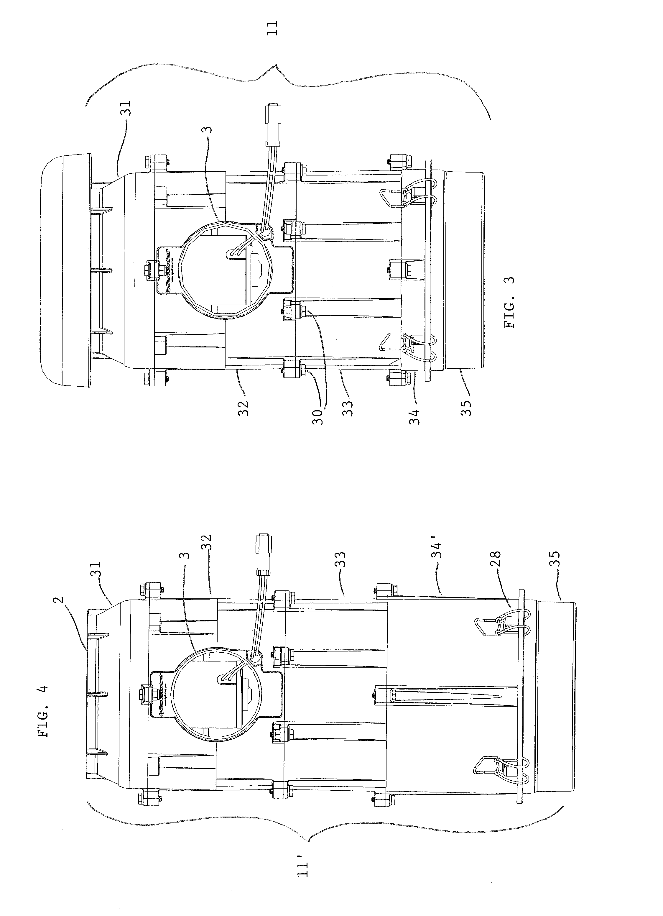
[0036]Referring now to the drawings, the powered air precleaner 1 of the disclosed embodiment comprises a flow path shown by the arrows B, B′ and B″ in FIGS. 1 and 6 and arrows 55 in FIG. 12 extending through the system from an inlet 2 to an outlet 3. A motor-driven fan 4 is located along the flow path to draw particulate debris laden air into the inlet and rotate it about a longitudinal axis A-A of the system to form a rotating flow that stratifies the debris laden air with the heaviest particles in the outermost orbits of the rotating flow. Ejector ports 5 and 5′, FIG. 6, are provided in a separator chamber end section 35 of the housing 11 for ejecting particulate debris laden air, B′, from the outermost orbits of the stratified rotating flow in the separator chamber 19 of the air precleaner.

[0037]The powered air precleaner 1 of the illustrated embodiment is equipped with an air inlet screen 6 and optionally a rain cap 7, FIG. 2, for an above-the-hood or other outdoor installation...


PUM

PropertyMeasurementUnit
timeaaaaaaaaaa
sizeaaaaaaaaaa
sizesaaaaaaaaaa

Abstract

A versatile compact air precleaner for separating heaver-than-air particulate debris from debris laden air has a retroflexed flow path through a separator chamber. A motor of a motor-driven fan is located in the flow path downstream from the separator chamber. A plurality of independently rotatably adjustable housing sections of a housing are formed with respective ones of the air precleaner debris laden air inlet, particulate debris ejector ports, clean air outlet, and mounts for mounting the air precleaner to a support to provide utility with multiple clean air outlet configurations, directions of ejection of particulate debris from the ejector ports, inlet configurations, precleaner sides for mounting, and filter sizes. A separator chamber end section including the ejector ports and the filter are connected forming a removable, disposable air filter cartridge which obviates ejector port clogging with change of filters.

Description

RELATED APPLICATION[0001]This application claims priority under 35 U.S.C. §119 of provisional application No. 61 / 513,201 filed Jul. 29, 2011. The entire disclosure of provisional application No. 61 / 513,201 is incorporated herein by reference.TECHNICAL FIELD[0002]The present invention is directed to an improved air precleaner, air cleaning method and disposable air filter cartridge for air precleaner for efficiently removing heavier-than-air particulate debris from debris laden air to provide a clean airflow to a device with which it is used. The air precleaner is versatile and compact for use in limited space applications having different configurations and clean airflow rate performance requirements in total airflow applications such as ventilation systems, as a fixed airflow provider for heat exchangers and heating and air conditioning systems, and with devices having a variable airflow demand, particularly internal combustion engines which exert a variable vacuum in their air int...

Claims


Application Information

Patent Timeline
Patent Type & Authority Applications(United States)
IPC IPC(8): B01D50/00B01D46/00B01D45/12
CPCB01D45/12B01D46/2411B01D46/2403B01D45/16B01D50/002B01D45/14B01D46/2414B01D50/20B01D46/0005
Inventor MOREDOCK, JAMES G.EHRENBERG, ERIC L.
Owner SY KLONE
Why Eureka
Try Eureka