Method and apparatus for debris mitigation for an electrical discharge source

a technology of electrical discharge source and debris, which is applied in the direction of optical radiation measurement, instruments, therapy, etc., can solve the problems of lpp radiation generation, cost, and primarily driven by the cost of laser diodes, and achieve the effect of reducing the efficiency of the transport of debris

Inactive Publication Date: 2005-05-03
EUV
View PDF6 Cites 2 Cited by
  • Summary
  • Abstract
  • Description
  • Claims
  • Application Information

AI Technical Summary

Benefits of technology

[0010]Accordingly, the present invention is directed, in part, to a method and apparatus for mitigating the transport of debris generated and dispersed by an electrical discharge source. The method is based on th...

Problems solved by technology

The capabilities of conventional photolithographic techniques have been severely challenged by the need for circuitry of increasing density requiring higher resolution features.
While generation of EUV radiation by means of a LPP reduces or eliminates many of the problems associated with other sources of EUV radiation, such as production of damaging atomic and particulate debris, there are still significant problems associated with LPP radiation generation.
Chief among these is the cost, primarily driven by the cost of the laser diodes required to pump the lasers.
Moreover, the laser pump poses severe technological pro...

Method used


Image

  • Method and apparatus for debris mitigation for an electrical discharge source
  • Method and apparatus for debris mitigation for an electrical discharge source
  • Method and apparatus for debris mitigation for an electrical discharge source

Examples


Embodiment Construction

[0015]The present invention is directed to an improved electrical capillary discharge source, wherein the improvement provides for trapping of debris generated by the capillary discharge source by thermophoretic and electrostatic deposition.

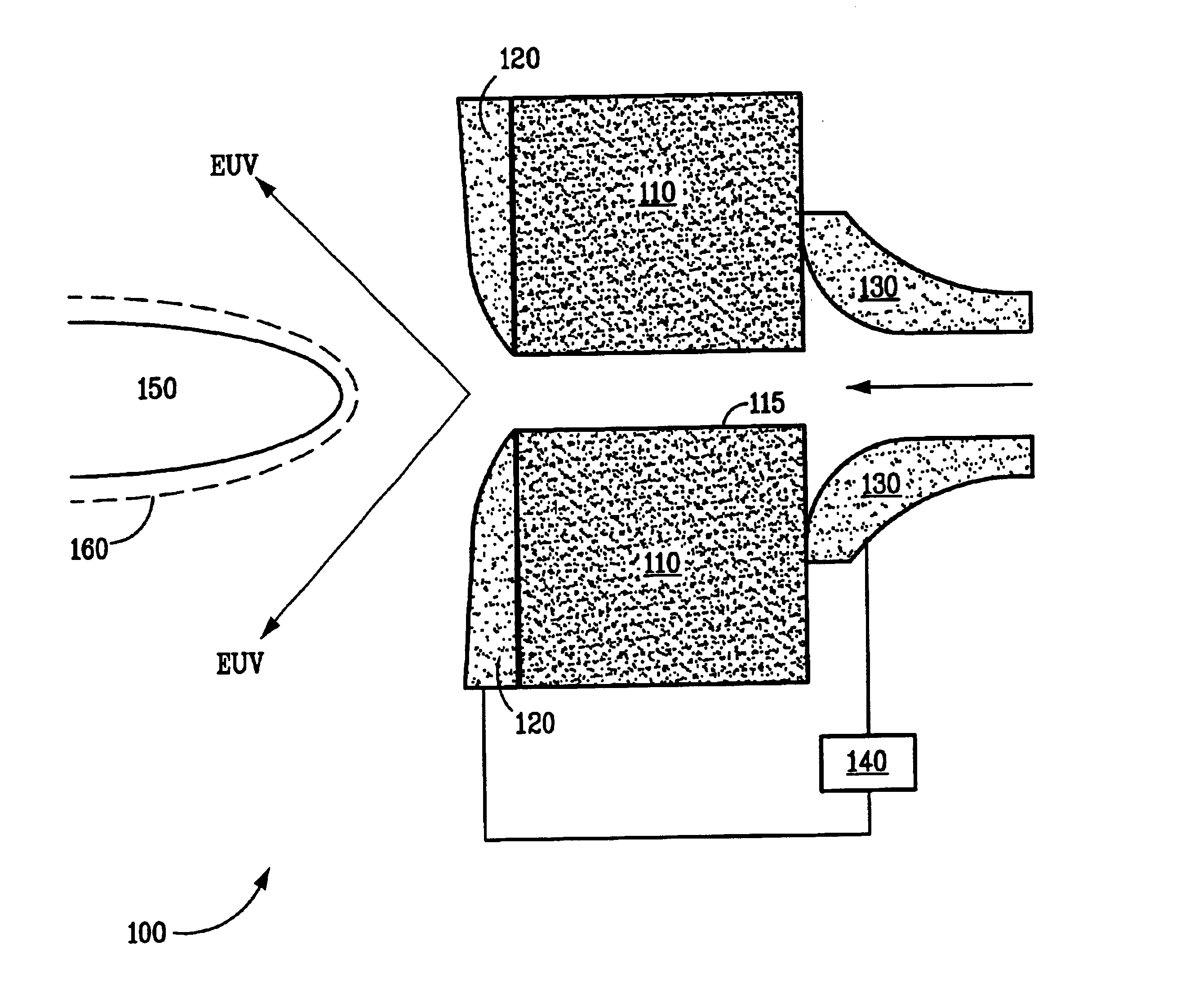
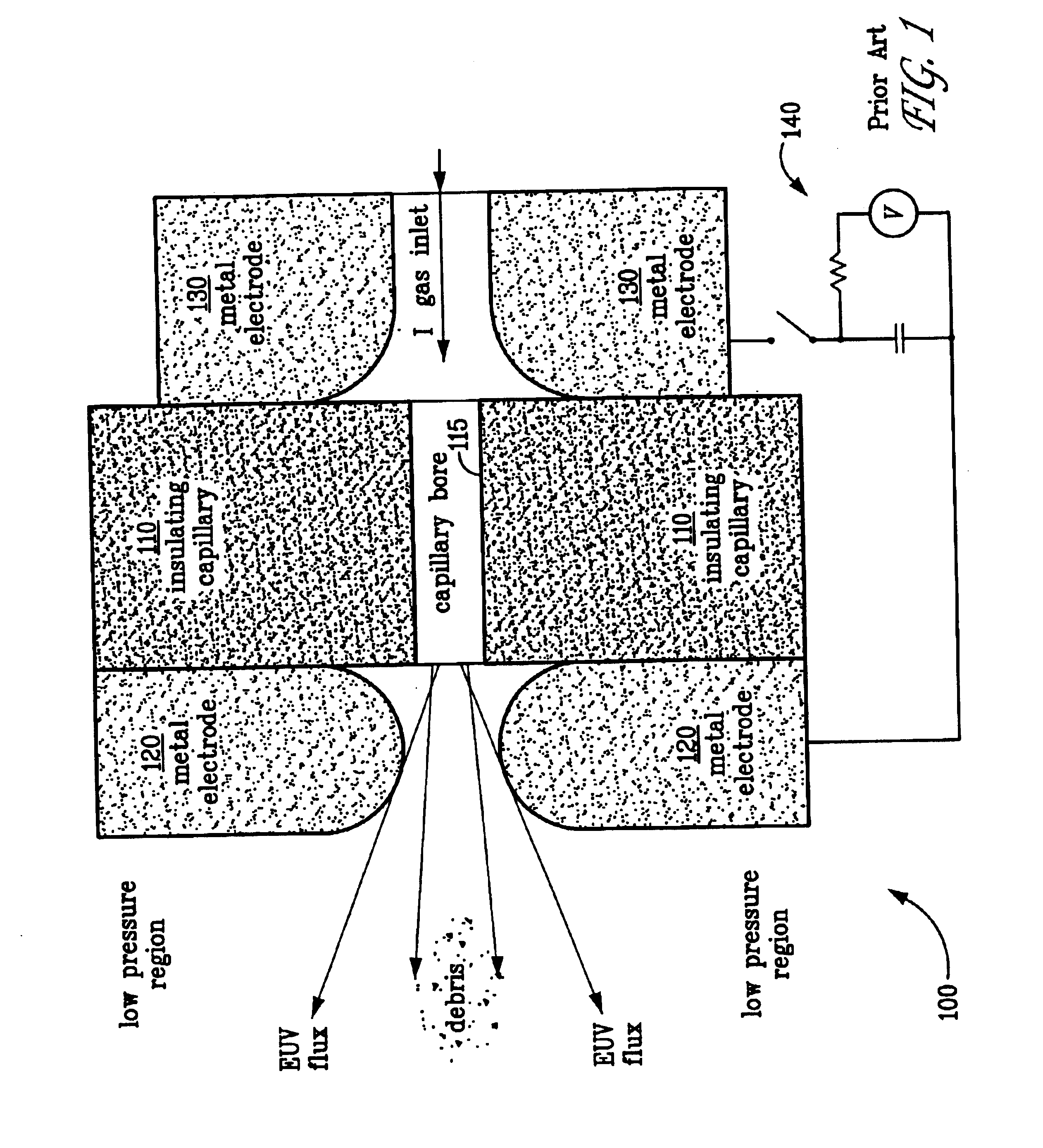
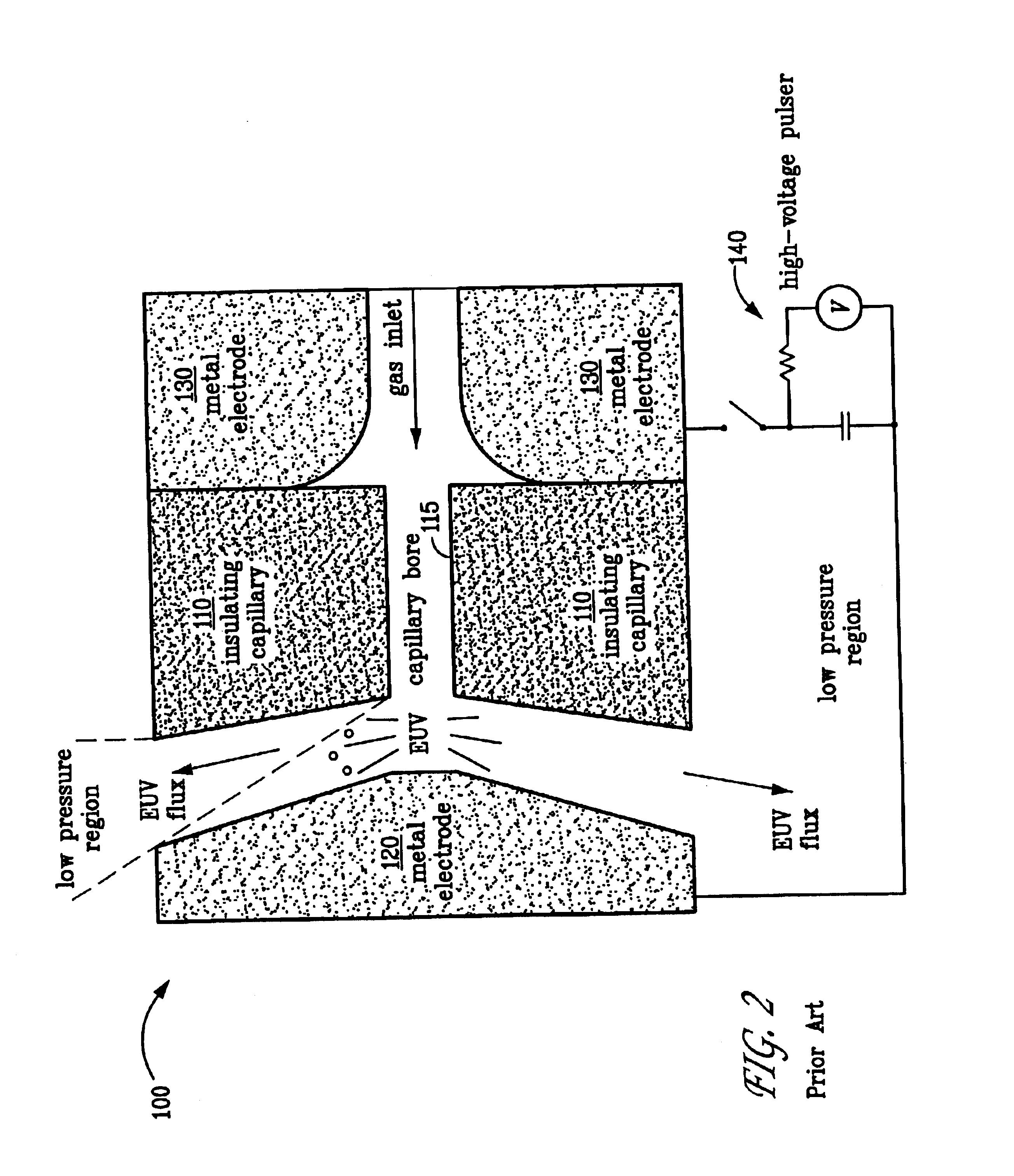
[0016]Referring now to FIG. 3 which illustrates a schematic cross-sectional view of an embodiment of the electrical capillary discharge source 100. As in the prior art discharge source illustrated in FIG. 1, the present electrical discharge source comprises an insulating disc 110, typically fabricated from an electrical insulator material such as a ceramic material, having an axial capillary bore 115, a front electrode 120 and a rear electrode 130, disposed on either side of insulating disc 110, each having an aperture aligned with capillary bore 115. Xenon gas flows through capillary bore 115 from rear electrode 130 to front electrode 120. A high voltage, high current electrical pulse is established across the front and rear electrodes by a sour...


PUM


Abstract

Method and apparatus for mitigating the transport of debris generated and dispersed from electric discharge sources by thermophoretic and electrostatic deposition. A member is positioned adjacent the front electrode of an electric discharge source and used to establish a temperature difference between it and the front electrode. By flowing a gas between the member and the front electrode a temperature gradient is established that can be used for thermophoretic deposition of particulate debris on either the member or front electrode depending upon the direction of the thermal gradient. Establishing an electric field between the member and front electrode can aid in particle deposition by electrostatic deposition.

Description

STATEMENT OF GOVERNMENT INTEREST[0001]This invention was made with Government support under contract no. DE-AC04-94AL85000 awarded by the U.S. Department of Energy to Sandia Corporation. The Government has certain rights in the invention.CROSS-REFERENCE TO RELATED APPLICATIONS[0002]Not applicable.FIELD OF THE INVENTION[0003]The present invention pertains generally to method and apparatus for mitigating the transport of debris generated and dispersed by electrical discharge sources used, in particular, for generating extreme ultraviolet radiation by the use of thermophoretic and electrostatic deflection and deposition.BACKGROUND OF THE INVENTION[0004]Photolithography is a well-known technique for applying patterns to the surface of a workpiece, such as a circuit pattern to a semiconductor chip or wafer. This technique has the advantage of being able to faithfully reproduce small and intricate patterns. Traditional photolithography involves applying electromagnetic radiation (light) t...

Claims


Application Information

Patent Timeline
IPC IPC(8): G03F7/20H05G2/00
CPCB82Y10/00G03F7/70033H05G2/003G03F7/70916H01J2893/0063
Inventor KLEBANOFF, LEONARD E.SILFVAST, WILLIAM T.RADER, DANIEL J.
Owner EUV
Why Eureka
Try Eureka