Elastomeric riblets

a technology of riblets and elastomers, applied in the field of surface geometries, can solve the problems of reducing the durability of the surface, reducing the service life of the structure, so as to reduce the transportation, improve the long-term durability, and reduce the effect of static charging

Active Publication Date: 2010-11-11
THE BOEING CO
View PDF26 Cites 42 Cited by
  • Summary
  • Abstract
  • Description
  • Claims
  • Application Information

AI Technical Summary

Benefits of technology

[0011]In a further alternative methods for web processing, the complimentary tool is a roll-to-roll tool and a polymer layer, a metallic layer or a combination of polymer and metallic layers, such as an LSA, is deposited intermediate the adhesive layer and the elastomeric layer. A thin film coating or modification of the riblet exterior surface for decorative appearance and / or to provide electrical conductivity / resistance (to mitigate static charging), UV reflectivity or absorption (to improve long term durability in high solar / high altitude environments) and / or to reduce transport across the surface to improved oxidation and / or fluid resistance may be sputtered (or otherwise deposited) onto the complimentary tool prior to deposition of the high elongation elastomeric layer or deposited onto the high elongation elastomeric layer after removal from the complimentary tool. In modifications to these methods, ion implantation or chemical surface modification my be to form a layer or modified surface on the riblets.

Problems solved by technology

However in service use such as on an aircraft aerodynamic surface, polymers are relatively soft thus reducing the durability of the surface.
Existing solutions with polymeric tips may readily deform hundreds of percent with fingernail pressure and may be unrecoverable since the thermoplastic polymer (fluoropolymers such as THV or FEP for example) has “yielded” or the thermoset (structural epoxy for example) has fractured at relatively low strain.
Such structures may be undesirable in normal service use on an aircraft or other vehicle.

Method used


Image

  • Elastomeric  riblets
  • Elastomeric  riblets
  • Elastomeric  riblets

Examples


Embodiment Construction

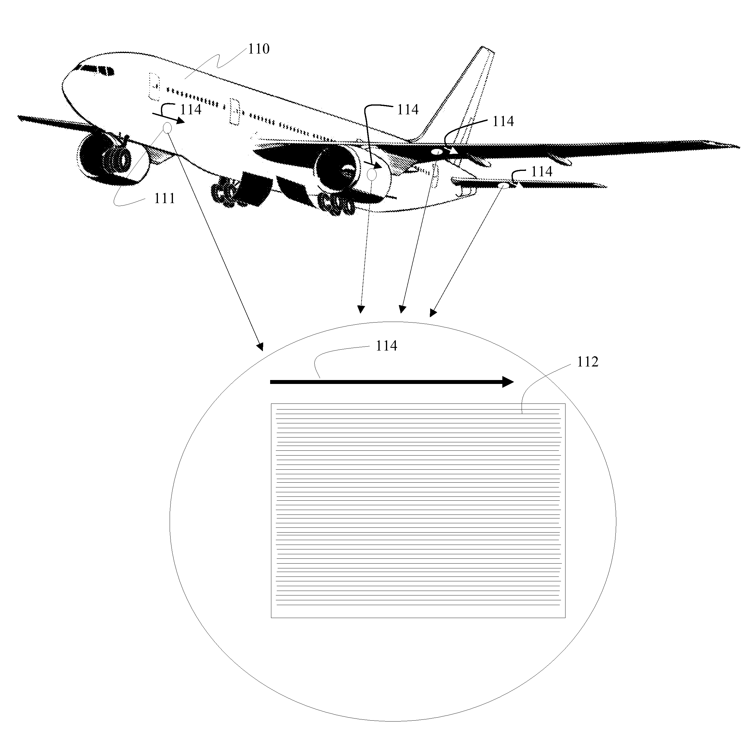
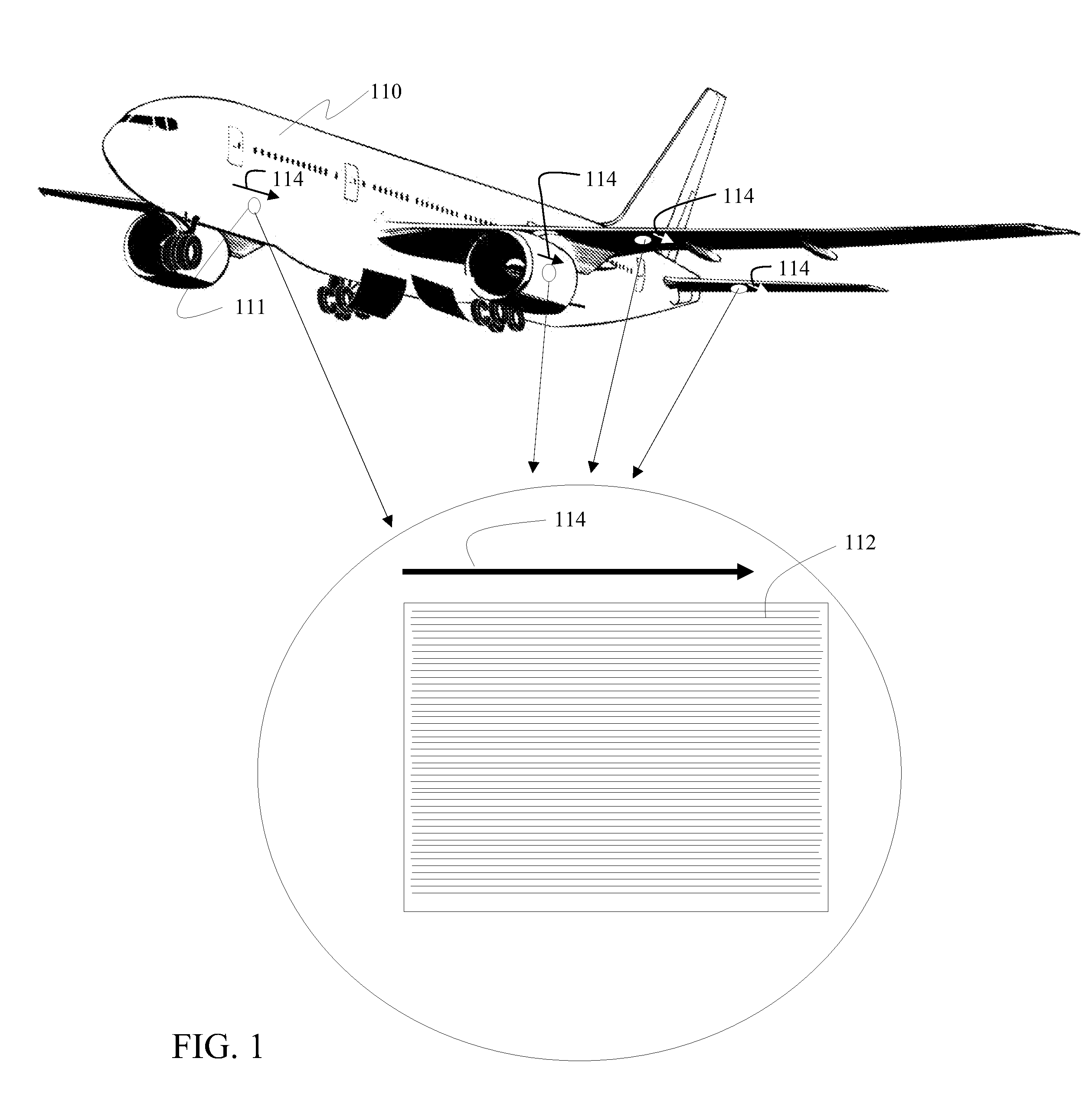
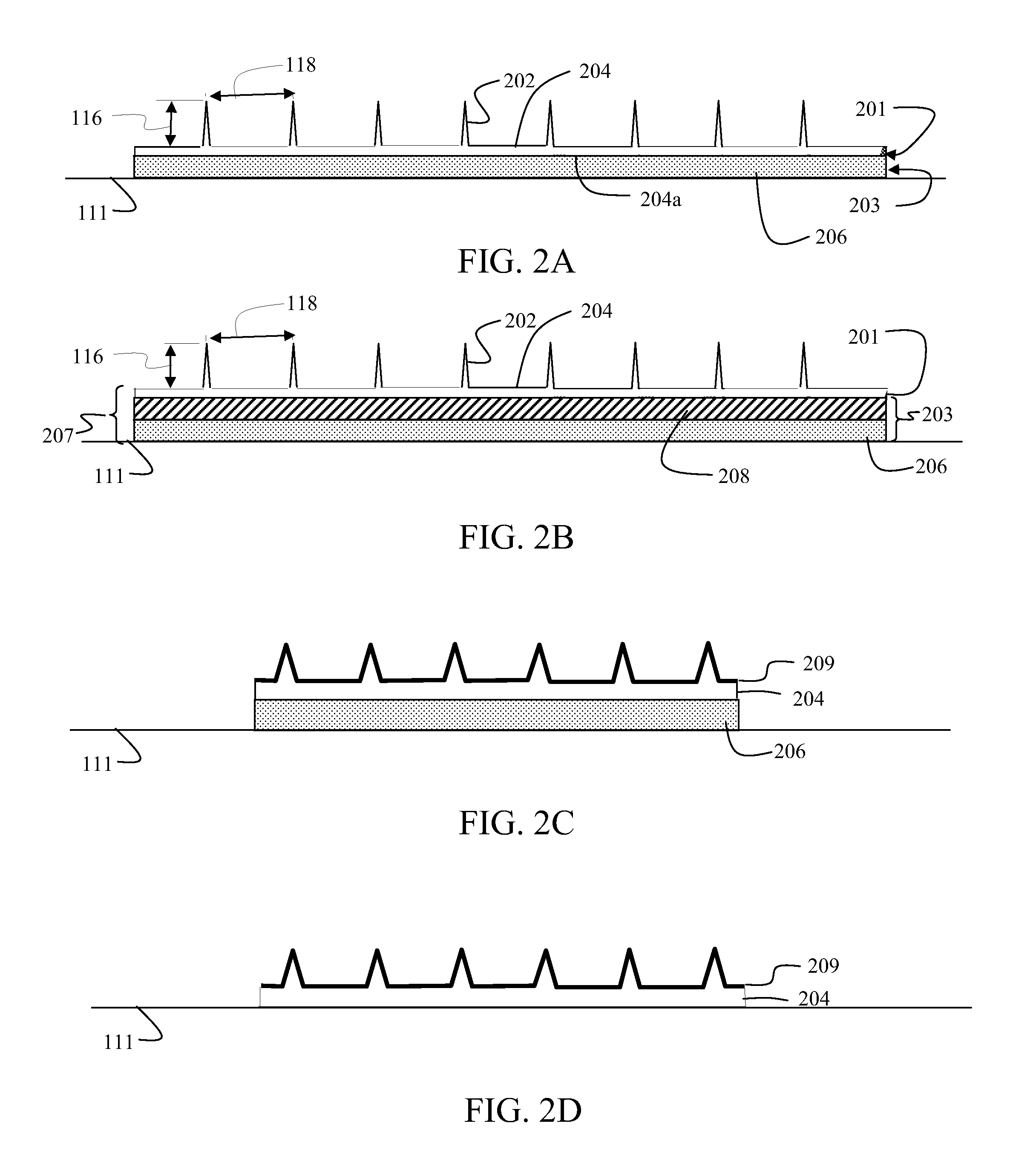
[0030]The embodiments disclosed herein provide riblets constructed with high elongation elastomeric materials that may be impacted by ground support equipment, ground support personnel or environmental hazards such as hail without permanent deformation / damage. These embodiments also allow an optimized structural design of riblets providing the capability for them to be thinner, lower weight, and more aerodynamically efficient. An exemplary embodiment of elastomeric riblets having a structure as will be described in greater detail subsequently is shown as a portion of an aerodynamic surface for an aircraft as shown in FIG. 1. The aircraft 110 employs a structure with a surface 111, shown enlarged, having multiple substantially parallel riblets 112 arranged parallel to the flow direction as represented by arrow 114. For the exemplary embodiment shown, the height dimension 116 perpendicular to the surface 111 is approximately 0.002 inch while the spacing 118 between the riblets is appr...


PUM

PropertyMeasurementUnit
elongationaaaaaaaaaa
heightaaaaaaaaaa
heightaaaaaaaaaa

Abstract

An array of aerodynamic riblets incorporates a high elongation elastomeric layer having spaced tips and optionally a protective cladding. The elastomeric layer may be adhered to an aerodynamic surface directly or as an appliqué in combination with one or more of an adhesive layer, one or more supporting polymer layers and a metal foil layer.

Description

REFERENCE TO RELATED APPLICATIONS[0001]This application is a continuation in part of U.S. patent application Ser. No. 12 / 361,840 entitled Rigid Tipped Riblets filed on Jan. 29, 2009 by inventors Diane C. Rawlings and Kevin R. Malone having attorney docket no. 08-0954, the disclosure of which is incorporated herein by reference. This application is copending with U.S. patent application Ser. No. 12 / 361,882 entitled Shape Memory Riblets by inventors Diane C. Rawlings and Terry L. Schneider having attorney docket no. 08-0936 and U.S. patent application Ser. No. 12 / 361,918 entitled Amorphous Metal Riblets by inventors Diane C. Rawlings and Stephen Christensen having attorney docket no. 08-0944 both filed on Jan. 29, 2009 the disclosures of which are incorporated herein by reference. This application is also copending with U.S. patent application Ser. No. ______ filed substantially concurrently herewith entitled Structurally Designed Aerodynamic Riblets by inventors Diane C. Rawlings, Ja...

Claims


Application Information

Patent Timeline
Patent Type & Authority Applications(United States)
IPC IPC(8): B64C1/00B32B37/12
CPCB32B15/06B32B25/08B64C21/10Y10T156/1039B29C65/4855B64C2230/26Y10T156/10Y02T50/166B32B7/12B32B15/02B32B15/08B32B15/20B32B25/02B32B25/14B32B27/281B32B27/283B32B27/285B32B27/286B32B27/288B32B27/304B32B27/32B32B27/322B32B27/34B32B27/36B32B27/38B32B3/30B32B2255/10B32B2255/102B32B2255/205B32B2264/02B32B2264/10B32B2307/202B32B2307/416B32B2307/50B32B2307/51B32B2307/714B32B2605/00B32B2605/18Y02T50/10
Inventor RAWLINGS, DIANE C.BURG, ALAN G.
Owner THE BOEING CO
Why Eureka
Try Eureka