Compound heat pipe, method of manufacturing the same, heat exchanger and heat exchanger system using the same

A technology of heat exchange system and heat exchanger, which is applied in the field of heat transfer tubes, can solve the problems of reduced heat conduction performance, and achieve the effects of light cost, superior heat transfer performance, and excellent conductivity

Active Publication Date: 2012-07-04
LG ELECTRONICS INC
View PDF10 Cites 2 Cited by
  • Summary
  • Abstract
  • Description
  • Claims
  • Application Information

AI Technical Summary

Problems solved by technology

The existence of such gaps reduces the heat transfer performance between the fluid flowing inside the heat transfer tube and the fluid flowing outside the heat transfer tube

Method used


Image

  • Compound heat pipe, method of manufacturing the same, heat exchanger and heat exchanger system using the same
  • Compound heat pipe, method of manufacturing the same, heat exchanger and heat exchanger system using the same
  • Compound heat pipe, method of manufacturing the same, heat exchanger and heat exchanger system using the same

Examples


Embodiment Construction

[0032] Hereinafter, preferred embodiments of the present invention will be described in detail with reference to the accompanying drawings. Prior to this, the terms or words used in this specification and claims should not be limited to common interpretations or dictionary interpretations, but should be based on the inventor's ability to properly define his invention in the most optimal way. The principles of the concepts of the terms are interpreted as the meanings and concepts consistent with the technical ideas of the present invention.

[0033] Therefore, the embodiments described in this specification and the structures shown in the accompanying drawings are only the most preferred embodiments of the present invention, and do not represent all technical ideas of the present invention, so it should be understood that the Various equivalents and modifications that can replace the present invention may also exist from time to time.

[0034] First, a number of new terms appe...


PUM

PropertyMeasurementUnit
thicknessaaaaaaaaaa
thicknessaaaaaaaaaa

Abstract

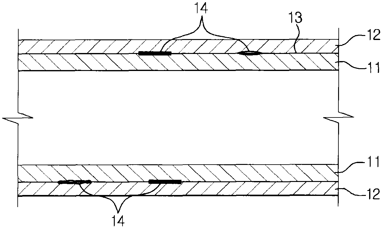
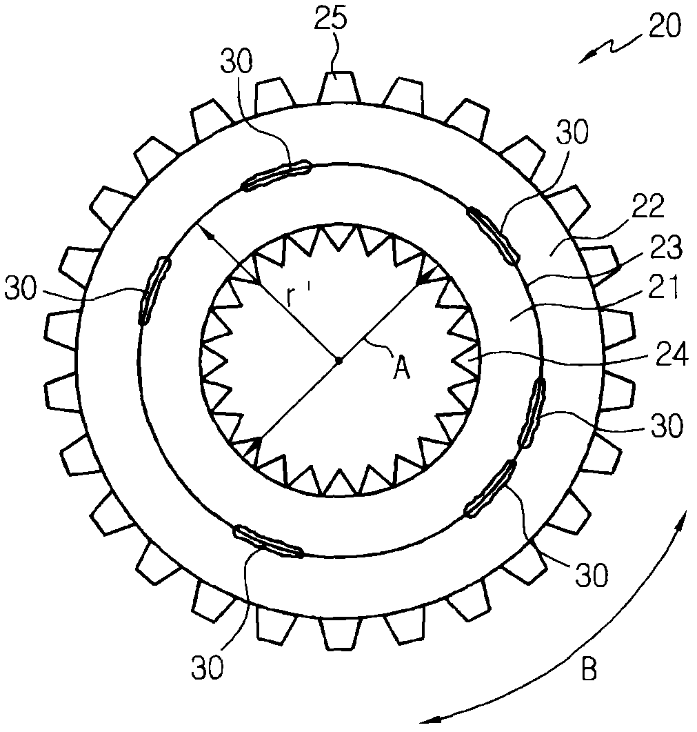
The compound heat pipe according to the present invention may overcome physical limits, which a single metal pipe might have, by integrally joining different metal pipes having different physical properties, forming ridges on an inner surface thereof the pipe and protrusions on an outer surface thereof and may first increase heat transfer capability by increasing the heat transfer area between the pipe and fluid. Further, the compound heat pipe according to the present invention may secondly increase the heat transfer capability by setting the noncontact rate to be 30% or less so that the heat transfer rate of the compound heat pipe in the radial direction may be optimized.

Description

technical field [0001] The invention relates to a heat transfer tube used in a heat exchanger, in particular to a composite heat transfer tube composed of metal materials with different physical properties. Background technique [0002] Generally, industrial equipment, heating and cooling equipment, various mechanical devices, and the like are equipped with a heat exchange system for performing a heat exchange function. In such heat exchange systems, heat transfer tubes are widely used as metal tubes for heat exchange. For example, in the absorber and evaporator of an absorption refrigerator that utilizes the principle that the liquid solubility of refrigerant vapor varies with temperature and pressure, for the heat exchange between cooling water and absorption liquid and between cold water and refrigerant Use heat transfer tubes. Also, in the evaporator of the turbo refrigerator, heat transfer tubes are used for heat exchange between cold water and refrigerant (R134a). ...

Claims


Application Information

Patent Timeline
Patent Type & Authority Applications(China)
IPC IPC(8): F28F1/42F28F21/08B21D53/06
CPCF28D15/0275Y02B30/62F28D15/0233F28F21/088Y10T29/4935
Inventor 金吉泳朴一权李亨准
Owner LG ELECTRONICS INC
Why Eureka
Try Eureka