Water tank structure of heat exchange water tank

A technology for exchanging water tanks and water tanks, which is applied to the types of heat exchangers, indirect heat exchangers, heat exchange equipment, etc., which can solve the problems of low heat transfer efficiency, long pipe length, and high cost, so as to increase fluid resistance, The effect of saving production cost and efficient heat transfer

Active Publication Date: 2015-01-07
巨浪(苏州)热水器有限公司
View PDF3 Cites 2 Cited by
  • Summary
  • Abstract
  • Description
  • Claims
  • Application Information

AI Technical Summary

Problems solved by technology

There are generally two types of heat exchanger devices in existing heat exchange tanks; one is a spiral coil, which conducts heat transfer through the coil and the medium in the water tank, but the heat of the coil in this type of heat exchange tank can only be Part of it is transferred to the medium in the water tank, and the heat transfer efficiency is not high. Another kind is to spirally wind the coil in the water tank. Although this structure increases the heat transfer efficiency, it requires its heat transfer. Longer tube lengths, resulting in higher costs

Method used


Image

  • Water tank structure of heat exchange water tank
  • Water tank structure of heat exchange water tank
  • Water tank structure of heat exchange water tank

Examples


Embodiment Construction

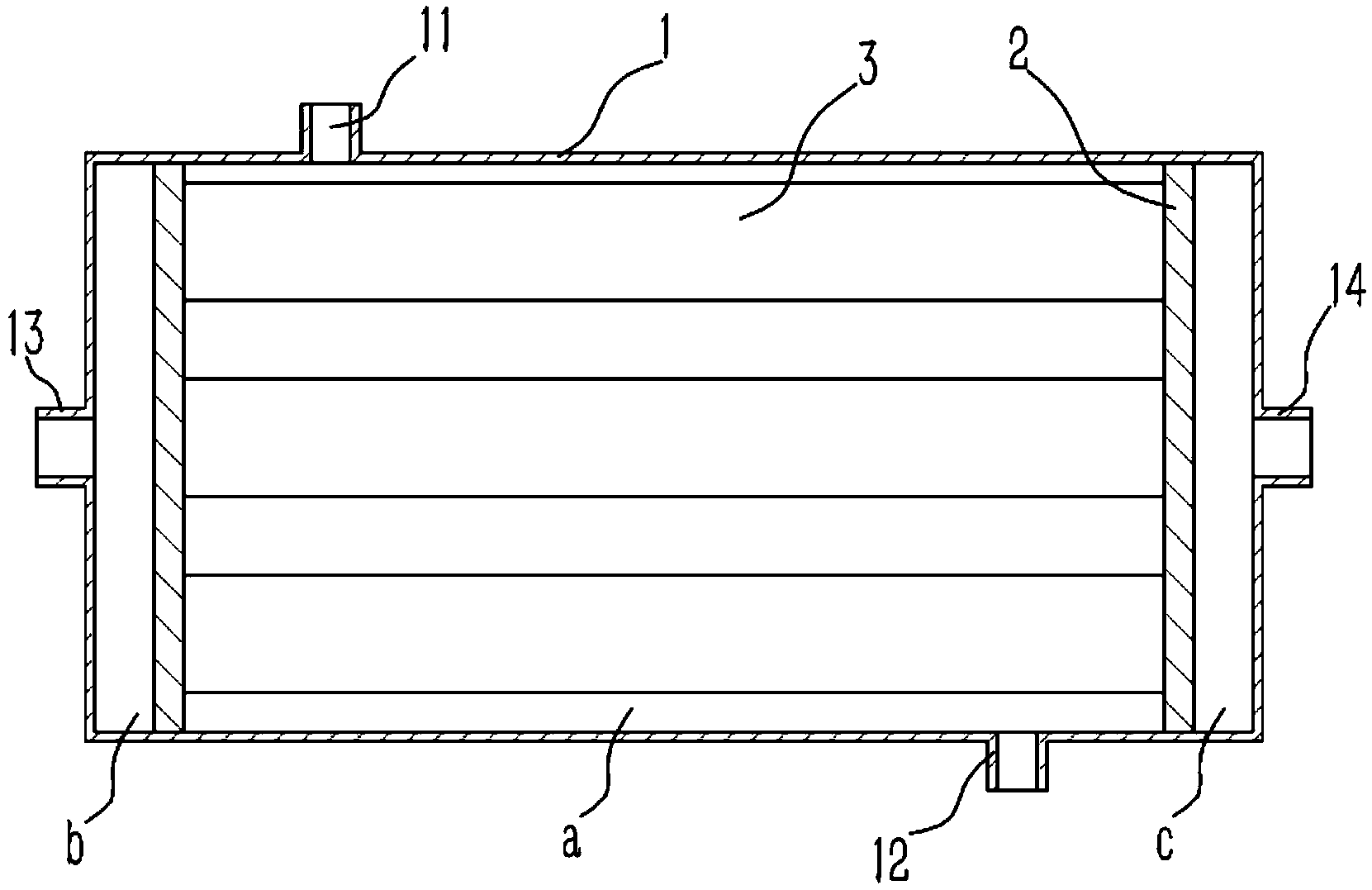
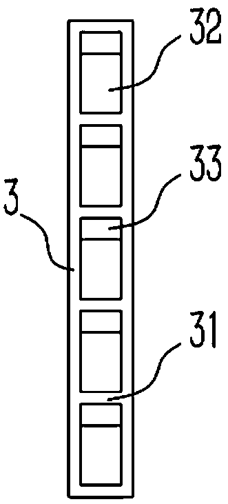
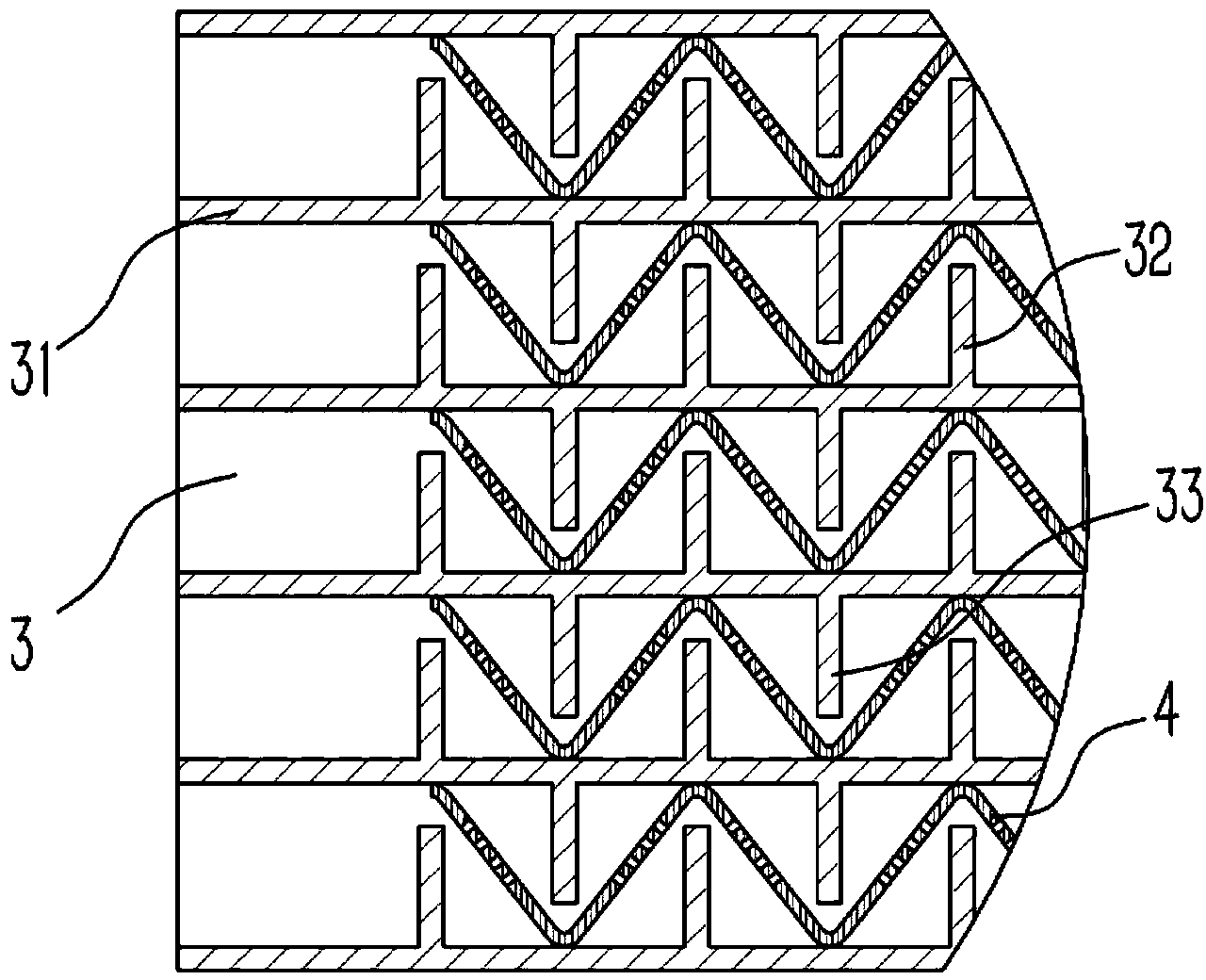
[0015] Example: see figure 1 , 2 , 3, a water tank structure of a heat exchange tank, including a rectangular flat water tank 1, the upper and lower ends of the flat water tank 1 are respectively formed with a water inlet 11 and a water outlet 12, and two sealing partitions 2 are fixed in the flat water tank 1 , the sealing partition 2 separates the inner cavity of the water tank into a refrigerant inlet chamber b, a water storage chamber a, and a refrigerant outlet chamber b, and the side walls of the flat water tank 1 where the refrigerant inlet chamber b and the refrigerant outlet chamber b are located are respectively formed with refrigerant Inlet 13 and refrigerant outlet 14, several rectangular heat dissipation pipes 3 are distributed in the water storage chamber a, and the two ends of the heat dissipation pipes 3 are respectively welded and fixed on the two sealing partitions 2 and connected with the refrigerant inlet chamber b and the refrigerant outlet The liquid cav...


PUM


Abstract

A water tank structure of a heat exchange water tank comprises a valve body, wherein a cylindrical valve cavity is formed in the valve body. An air inlet and an air outlet communicated with the valve cavity are formed at the upper end and the lower end of the valve body respectively. A reamed hole is formed on the inside wall of the valve body close to the air outlet end, and threads are formed on the inside wall of the reamed hole. A valve plate is arranged in the valve cavity of the valve body, a boss is formed on the upper end surface of the valve plate, a barrel-shaped protection cover is fixedly inserted and sleeved on the boss, a plurality of air inlet holes are formed on the protection cover, and the protection cover is connected into the air inlet of the valve body in an inserting way. Sealing pads are fixed on the valve plate surrounding the boss and press against the upper bottom surface of the valve body. A protection structure is added at the air inlet end on the basis of the existing hot water pollution discharge air inlet valve, the inner structure of the valve body is correspondingly modified, and therefore the pollution discharge air inlet valve has the function of preventing large-particle sundries from blocking the air inlet.

Description

Technical field: [0001] The invention relates to the technical field of water heaters, in particular to a water tank structure of a heat exchange tank. Background technique: [0002] The heat exchange tank generally means that the heat exchanger is built in the water tank, and the heat of the hot fluid in it is transferred to the cold fluid in the water tank through the heat exchanger. There are generally two types of heat exchanger devices in existing heat exchange tanks; one is a spiral coil, which conducts heat transfer through the coil and the medium in the water tank, but the heat of the coil in this type of heat exchange tank can only be Part of it is transferred to the medium in the water tank, and the heat transfer efficiency is not high. Another kind is to spirally wind the coil in the water tank. Although this structure increases the heat transfer efficiency, it requires its heat transfer. The length of the pipe is longer, which increases the cost. Invention con...

Claims


Application Information

Patent Timeline
Patent Type & Authority Applications(China)
IPC IPC(8): F28D1/06F28F1/40
Inventor 陈凯陈金红洪一波
Owner 巨浪(苏州)热水器有限公司
Why Eureka
Try Eureka