Liquid crystal display device and planar light source device provided to liquid crystal display device

Inactive Publication Date: 2013-03-07
SHARP KK
View PDF0 Cites 3 Cited by
  • Summary
  • Abstract
  • Description
  • Claims
  • Application Information

AI Technical Summary

Benefits of technology

[0024]According to a liquid crystal display device in accordance with the present invention, foreign substances having entered the liquid crystal display device are likely to be collected on an uneven surface of or a slit of a frame provided in a planar light source device. This causes, even in a case where foreign substances enter the liquid crystal display device, the foreign substances to be less likely to enter a gap between the planar ligh

Problems solved by technology

However, providing the double-sided adhesive tape 6 along two sides of the resin frame 13 poses a risk that f

Method used


Image

  • Liquid crystal display device and planar light source device provided to liquid crystal display device
  • Liquid crystal display device and planar light source device provided to liquid crystal display device
  • Liquid crystal display device and planar light source device provided to liquid crystal display device

Examples


Example

Summary of Planar Light Source Device 1

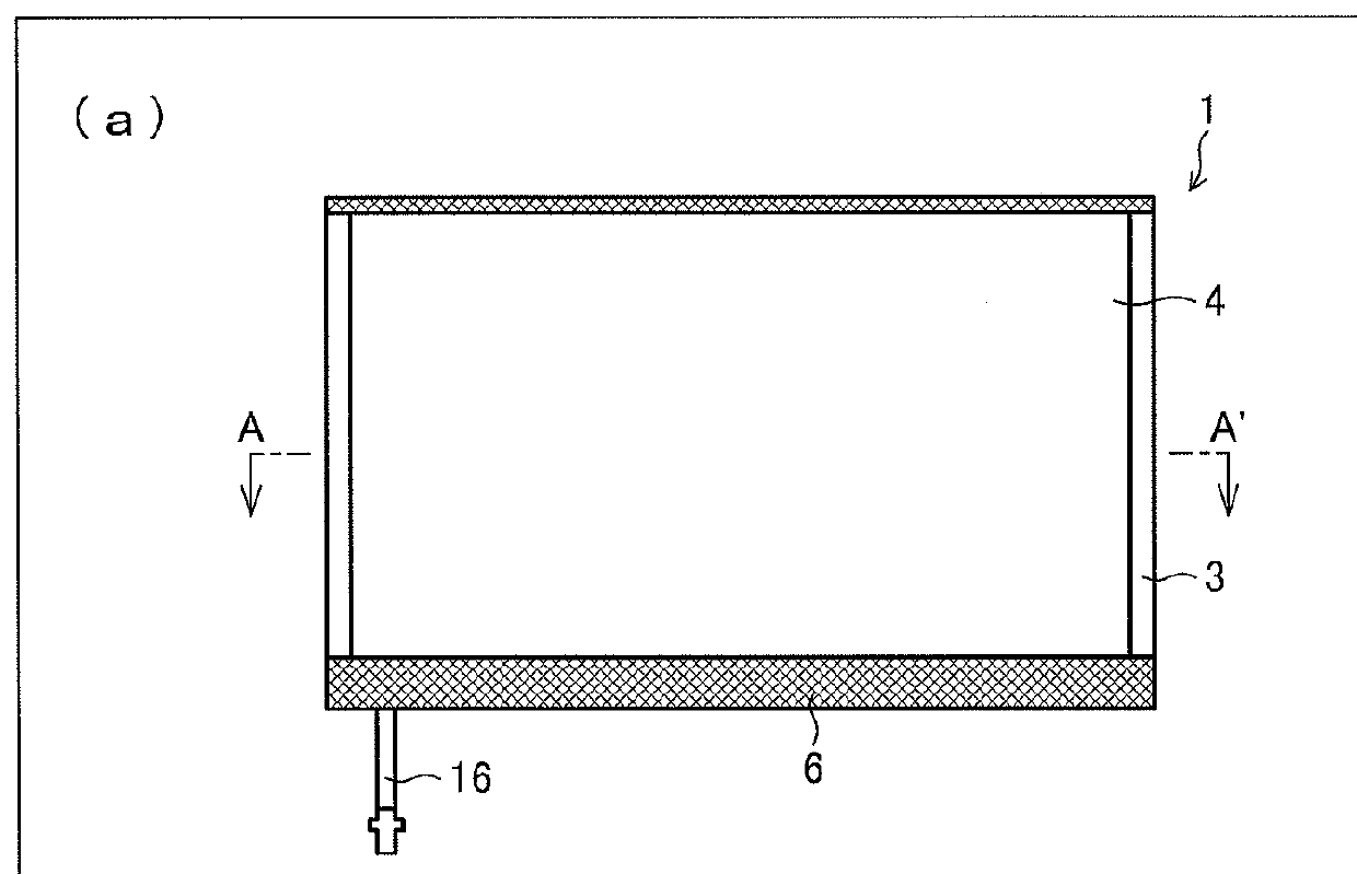
[0050]A liquid crystal module (liquid crystal display device) is basically made up of a backlight section and a liquid crystal display element section and has a planar light source device as the backlight section and a liquid crystal panel as the liquid crystal display element section. A planar light source device in accordance with the present embodiment will be schematically described with reference to FIG. 2. (a) of FIG. 2 is a view of a planar light source device 1 observed from a light-exit-plane side. (b) of FIG. 2 is a view of the planar light source device 1 taken along the line A-A′ of (a) of FIG. 2.

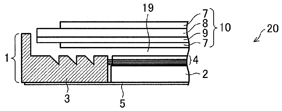
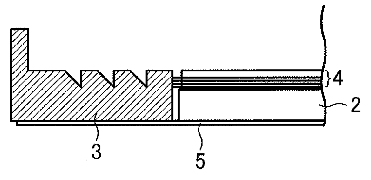
[0051]As illustrated in (b) of FIG. 2, the planar light source device 1 includes a light guide plate 2, a resin frame 3, an optical film 4, a reflective film 5, and a light source (not illustrated). The light guide plate 2 is provided inside the resin frame 3 provided on the reflective film 5, and the optical film 4 is further provided on t...


PUM


Abstract

A liquid crystal module includes a planar light source device and a liquid crystal panel which are combined together by use of a double-sided adhesive tape (not illustrated). The double-sided adhesive tape is provided on a part of a resin frame, which part is on a light-exit-plane side. A part of the resin frame, which part is not provided with the double-sided adhesive tape, has an uneven surface or has a slit on a surface thereof. In other words, a part of the resin frame, which part corresponds to sections where the planar light source device and the liquid crystal panel are not combined together, has an uneven surface or has a slit on a surface thereof.

Description

TECHNICAL FIELD[0001]The present invention relates to a liquid crystal display device and a planar light source device provided in the liquid crystal display device.BACKGROUND ART[0002]Mobile information devices, such as laptop personal computers, PDAs (Personal Data Assistant), portable gaming devices, and mobile phones, are becoming prevalent in today's market place. Liquid crystal modules are widely used for displays of such mobile information devices. A liquid crystal module is basically made up of a backlight section and a liquid crystal display element section, and has (i) a planar light source device as the backlight section and (ii) a liquid crystal panel as the liquid crystal display element section. A conventional liquid crystal module is illustrated by FIG. 8. FIG. 8 is a view schematically illustrating a cross section of a conventional liquid crystal display device 30.[0003]As illustrated in FIG. 8, the liquid crystal module 30 includes: a planar light source device 11 a...

Claims


Application Information

Patent Timeline
IPC IPC(8): G02F1/13357F21V8/00
CPCG02B6/0088G02F2001/133317G02F1/133615G02F1/133317
Inventor TANAKA, SHIGENORI
Owner SHARP KK
Why Eureka
Try Eureka