Transmission for electric bicycles for detecting a torque and related method for electric bicycles for detecting a torque

Inactive Publication Date: 2013-05-09
ROBERT BOSCH GMBH
View PDF2 Cites 4 Cited by
  • Summary
  • Abstract
  • Description
  • Claims
  • Application Information

AI Technical Summary

Benefits of technology

[0020]In contrast to numerous known sensors, the present invention also makes possible the reversal

Problems solved by technology

For this reason, they are particularly prone to error

Method used


Image

  • Transmission for electric bicycles for detecting a torque and related method for electric bicycles for detecting a torque
  • Transmission for electric bicycles for detecting a torque and related method for electric bicycles for detecting a torque
  • Transmission for electric bicycles for detecting a torque and related method for electric bicycles for detecting a torque

Examples


first embodiment

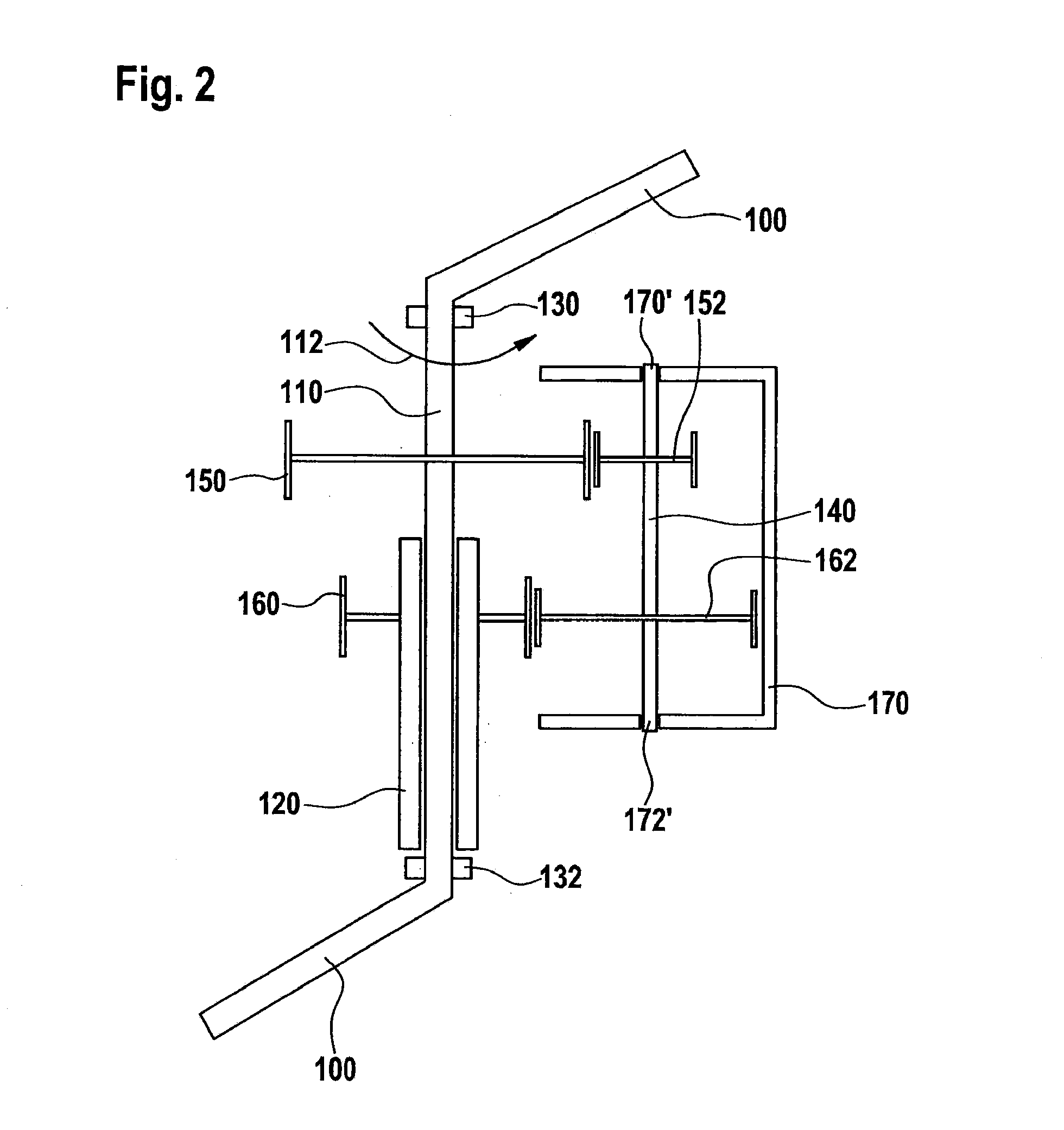
[0034]FIG. 2 shows the transmission according to the present invention, having crank 100, crank shaft 110 which is supported rotatably by bearings 130, 132, in order to be able to carry out a rotation according to arrow 112. On crank shaft 110, drive-side crank drive shaft wheel 150 is situated torsionally fixed and output-side hollow shaft wheel 160 is situated rotatably. Sensor shaft 40 has a drive-side sensor shaft wheel 152 and an output-side sensor shaft wheel 162, which are in engagement with wheels 150 and 160 respectively. The frame has an U-shaped extension, the two opposite legs having the rotary bearings 170′, 172′. The sensor shaft is rotatably supported in a frame 170 by rotary bearings 170′, 172′. The force is measured by a force sensor that is not shown, via which frame 170 is supported. The support not shown, via which the force sensor holds the frame, takes up forces in the tangential direction (with respect to the rotation of the sensor shaft or the pedal crank sha...

second embodiment

[0036]FIG. 3 shows the transmission according to the present invention, having a pedal crank shaft or crank shaft 210 at whose ends fastening elements 200 for pedal cranks are provided. On crank shaft 210, a hollow shaft 220 is rotatably supported via rotary bearings 222 and 222′. The crank shaft is supported on one side by a rotary bearing 230 and on the other side by a rotary bearing 232, which is located on the hollow shaft, via rotary bearing 222 between hollow shaft 220 and crank shaft 210 so that the crank shaft is also supported. Hollow shaft 220 at one end has a radially extending protuberance 224, which provides fastening elements (not shown) for the output drive.

[0037]A frame 270 is fastened on the pedal crank via rotary bearings 275 and 275′, which carries a sensor shaft 240 via rotary bearings 271, 272. On sensor shaft 240, a first wheel 252 (drive-side sensor shaft wheel) and a second wheel 262 (output-side sensor shaft wheel) are fastened, only one of the wheels (wheel...

third embodiment

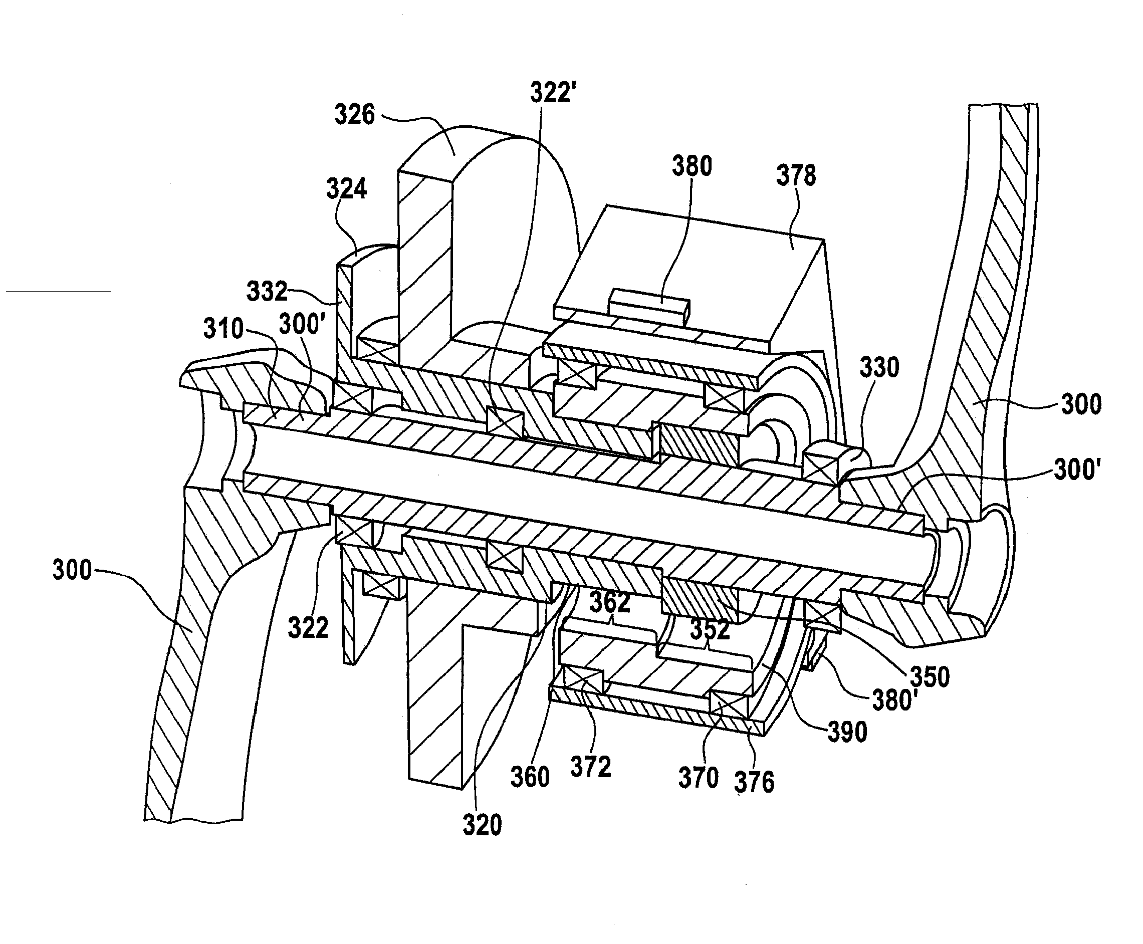
[0040]FIG. 4 shows the transmission according to the present invention, having a pedal crank shaft or crank shaft 310, on which, at fastening locations 300′, cranks 300 are situated at both ends of crank shaft 310. On crank shaft 310, a hollow shaft 320 is rotatably supported via rotary bearings 222, 322′ that are offset axially with respect to each other. Hollow shaft 320 has at its end, that is opposite to the end of the hollow shaft that faces the sensor transmission, a connecting possibility (in the form of a protuberance 324) for a sprocket wheel 324 for driving a rear wheel of the bicycle. On hollow shaft 320 there is also situated a drive element in the form of a toothed wheel 326, via which an additional torque of a motor is able to be applied to hollow shaft 320. A rotary bearing 332 supports hollow shaft 320 (and consequently also crank shaft 310, and a rotary bearing 330 supports crank shaft 310 at the opposite end of crank shaft 310.

[0041]On crank shaft 310 a crank drive...


PUM


Abstract

A transmission for electric bicycles to detect a torque applied to a pedal crank shaft, includes a pedal crank shaft upon which the torque acts, a hollow shaft configured to connect to an output, through which the pedal crank shaft extends coaxially, and which is supported rotatably with respect to the pedal crank shaft, a sensor shaft offset in parallel with respect to the pedal crank shaft and a force sensor connected to the sensor shaft. The transmission includes a drive-side sensor transmission and an output side sensor transmission. The drive-side sensor transmission connects the pedal crank shaft to the sensor shaft and the output-side sensor transmission connects the sensor shaft to the hollow shaft, which is configured to be connected to an output, and the drive-side sensor transmission has a gear ratio which differs from the gear ratio of the output-side sensor transmission. A corresponding method is also described.

Description

FIELD OF THE INVENTION[0001]The present invention relates to a transmission for electric bicycles to detect a torque applied to a pedal crank shaft.BACKGROUND INFORMATION[0002]In the field of the present invention, i.e. particularly the field of electric bicycles and related pedal force sensors, there are mechanisms for torque detection, in order to conclude upon the cyclist power with the aid of the torque with which the pedal crank is being actuated. The cyclist power or a comparable quantity is used as an input quantity in the regulation of an electric auxiliary motor of electric bicycles. The sensors used are provided directly at exposed locations and fastened to elements via which the entire torque is transmitted. For this reason, they are particularly prone to error.[0003]Besides solutions in which a force is ascertained directly by detection at the pedal crank shaft or by force sensors situated on the pedals, there are approaches that are in German document DE 698 20 41 T2. I...

Claims


Application Information

Patent Timeline
IPC IPC(8): B62M3/16G01D7/02
CPCB62M6/50Y10T74/2164G01D7/02B62M3/16
Inventor AYDOGAN, SERDARZLINDRA, MARTINBRAUN, SIGMUND
Owner ROBERT BOSCH GMBH
Why Eureka
Try Eureka