
Power supply system and rechargeable battery used in the system

a technology of power supply system and rechargeable battery, which is applied in the direction of cell components, sustainable manufacturing/processing, coupling device connection, etc., can solve the problems of shortening the time of use, consuming more power of powerful electronic devices, and limited capacity stored in these batteries

Inactive Publication Date: 2013-06-27
HONG FU JIN PRECISION IND (SHENZHEN) CO LTD +1
View PDF52 Cites 2 Cited by
  • Summary
  • Abstract
  • Description
  • Claims
  • Application Information

AI Technical Summary

Benefits of technology

The patent text is discussing the problem of portable electronic devices such as smart phones using spare batteries with limited capacity, and the difficulty for users to determine the remaining capacity of these batteries. Additionally, these batteries do not support hot swapping, which means users need to turn off the electronic device first and then detach and replace batteries, which interrupts the user's work and affects working efficiency. The patent aims to provide a solution to these problems.

Problems solved by technology

The powerful electronic devices consume more power, and time of use is therefore shortened.
However, the capacity stored in these batteries is limited, and it is difficult for user to learn how much residual capacity all these batteries keep.
As well these batteries do not support hot swapping, so users need to turn off the electronic device first, and then detach and replace batteries for these electronic devices, which interrupt the user's work and affect working efficiency.

Method used


Image

  • Power supply system and rechargeable battery used in the system
  • Power supply system and rechargeable battery used in the system
  • Power supply system and rechargeable battery used in the system

Examples


Embodiment Construction

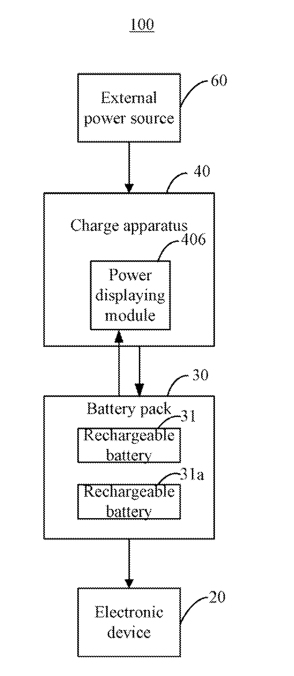
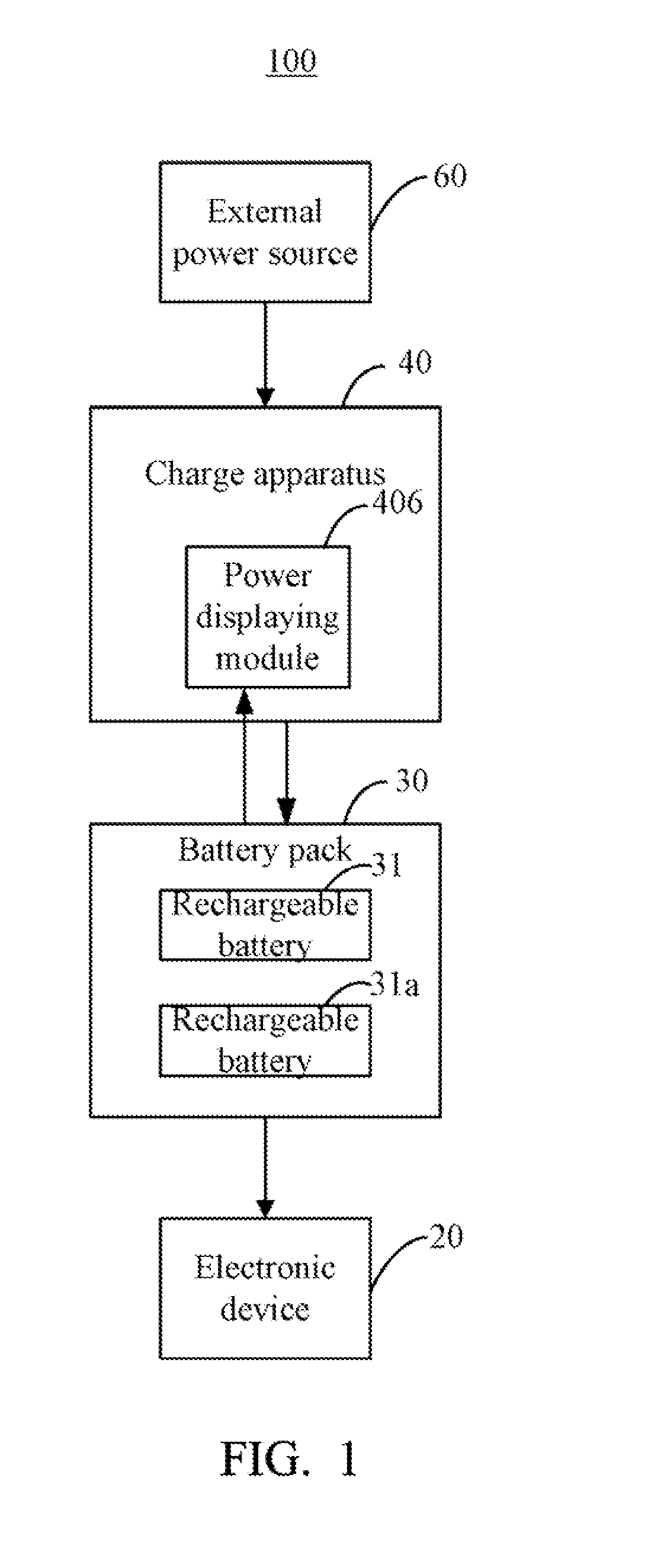
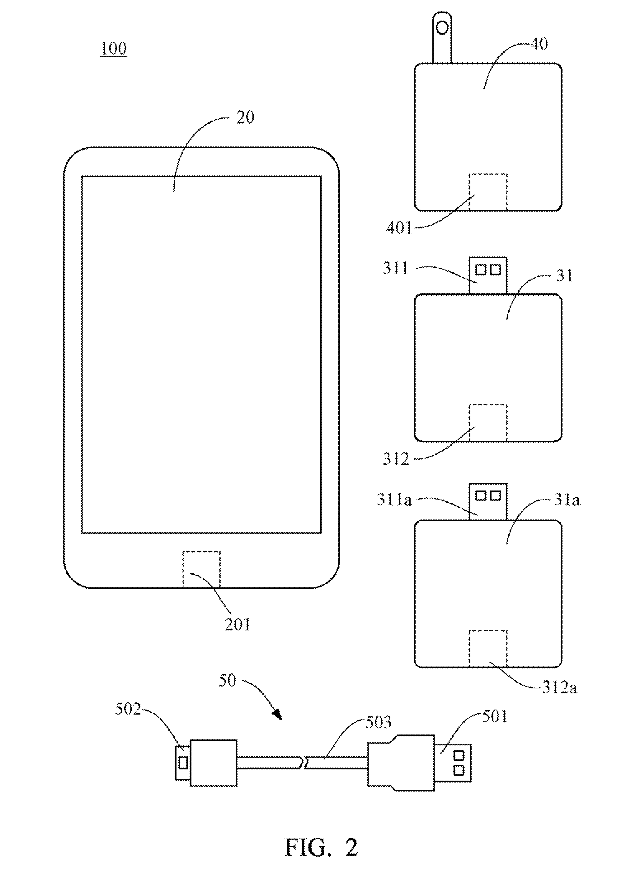
[0012]FIG. 1 shows a power supply system 100 of one embodiment. The power supply system 100 includes a portable electronic device 20, a battery pack 30 and a charge apparatus40. The electronic device 20 includes but not limited to mobile phone, PDA, for example. The battery pack 30 includes a number of rechargeable batteries 31, and the battery pack 30 can be coupled to the charge apparatus 40 and the electronic device 20. The charge apparatus 40 is electrically connected to an external power source 60 to charge the rechargeable battery 31, and the battery pack 30 supplies power to the electronic device 20. In the embodiment, the battery pack 30 further feeds back its residual capacity value to the charge apparatus 40. The charge apparatus 40 includes a power displaying module 406, which is configured to display the residual capacity value of the battery pack 30, and indicate whether the battery pack 30 is full charged during a charging process. Therefore, users know how much power ...


PUM

PropertyMeasurementUnit
poweraaaaaaaaaa
power measurementaaaaaaaaaa
residual capacityaaaaaaaaaa

Abstract

A rechargeable battery includes a plug, a first socket, a capacity storage module and a power measurement module. The plug is configured for being plugged in either a first socket of a second similar rechargeable battery to constitute a battery pack or a second socket of a charge apparatus. In addition, the first socket either is configured for either receiving a plug of a third similar rechargeable battery to constitute the battery pack or being electrically coupled to a power input port of an electronic device. The power measurement module is electrically connected to the capacity storage module, and is configured to measure a residual capacity value of the capacity storage module, and feedback the measured residual capacity value to the charge apparatus. A related power supply system is also provided.

Description

BACKGROUND[0001]1. Technical Field[0002]The present disclosure relates to power supply system and rechargeable battery that is being used in the system.[0003]2. Description of Related Art[0004]Functions of portable electronic devices such as smart phones have become more versatile and more powerful. The powerful electronic devices consume more power, and time of use is therefore shortened. Such that, users usually need to carry one or more spare batteries. However, the capacity stored in these batteries is limited, and it is difficult for user to learn how much residual capacity all these batteries keep. As well these batteries do not support hot swapping, so users need to turn off the electronic device first, and then detach and replace batteries for these electronic devices, which interrupt the user's work and affect working efficiency.[0005]Therefore, a power supply system, which overcomes the afore mentioned limitations is required.BRIEF DESCRIPTION OF THE DRAWINGS[0006]Many asp...

Claims


Application Information

Patent Timeline
Patent Type & Authority Applications(United States)
IPC IPC(8): H01M2/20H02J7/00H01M50/503H01M50/569
CPCH01M2/204H02J7/0013H02J7/0063H01R31/065H02J7/0054H02J2007/0062H01M10/052H02J7/342Y02E60/10Y02P70/50H01M50/569H01M50/503H02J7/00
Inventor TANG, CHIANG-KUOGUAN, YA-MINGLI, ZHI-GUOCHUNG, SHIN-HONG
Owner HONG FU JIN PRECISION IND (SHENZHEN) CO LTD
Learn More