
Electronic sphygmomanometer

a sphygmomanometer and electronic technology, applied in the field of sphygmomanometers, can solve the problems of complex relay circuits or analog switching circuits, inability to use the same cpu as the conventional electronic sphygmomanometer, and inability to use the same cpu as the conventional sphygmomanometer, etc., to achieve the effect of improving the reliability of blood pressure measurement values

Active Publication Date: 2017-02-21
OMRON HEALTHCARE CO LTD
View PDF24 Cites 2 Cited by
  • Summary
  • Abstract
  • Description
  • Claims
  • Application Information

AI Technical Summary

Benefits of technology

This design enhances the reliability of blood pressure measurements by detecting sensor abnormalities and reducing power consumption, while maintaining a compact and cost-effective circuit scale, thus addressing the limitations of previous technologies.

Problems solved by technology

Under this method, the scale of the circuit grows, and the same CPU as that employed in conventional electronic sphygmomanometers cannot be used.
A less expensive CPU that has only a single analog input terminal serving as a sensor input terminal requires a circuit for switching among the outputs from the multiple pressure sensors, which makes it necessary to employ a complex, high-cost relay circuit or analog switching circuit.
Meanwhile, there is the chance that the signals outputted from multiple pressure sensors will interfere with each other electromagnetically in the circuit, causing erroneous operation, and thus, it is necessary to ensure that the circuit board has a sufficient degree of electromagnetic insulation in order to obtain an accurate measurement.
Furthermore, using multiple pressure sensors simultaneously leads to an increase in the amount of power consumed in proportion to the number of pressure sensors, which reduces the number of times the sphygmomanometer can be used, particularly in battery-operated products.
CPUs that have a large circuit scale also consume more power.

Method used


Image

  • Electronic sphygmomanometer
  • Electronic sphygmomanometer
  • Electronic sphygmomanometer

Examples


Embodiment Construction

[0038]Hereinafter, an electronic sphygmomanometer according to one or more embodiments of this invention will be described with reference to the drawings. When numbers, amounts, and so on are discussed in the following embodiments, it should be noted that unless explicitly mentioned otherwise, the scope of the present invention is not necessarily limited to those numbers, amounts, and so on.

[0039]Furthermore, in the case where multiple embodiments are described hereinafter, it is assumed from the outset that the configurations of the respective embodiments can be combined as appropriate unless explicitly mentioned otherwise. In the drawings, identical reference numerals refer to identical or corresponding elements. There are also cases where redundant descriptions are omitted.

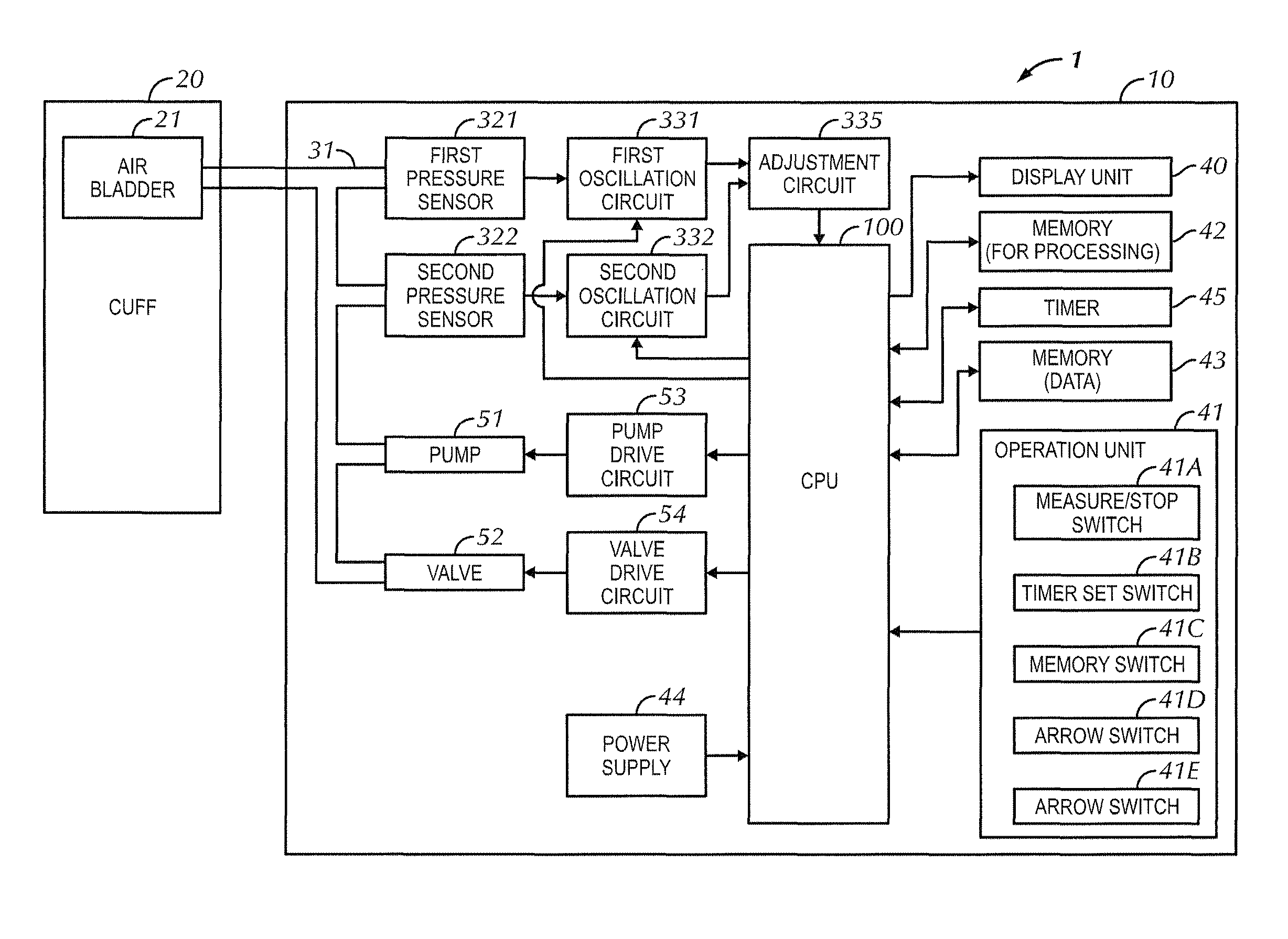
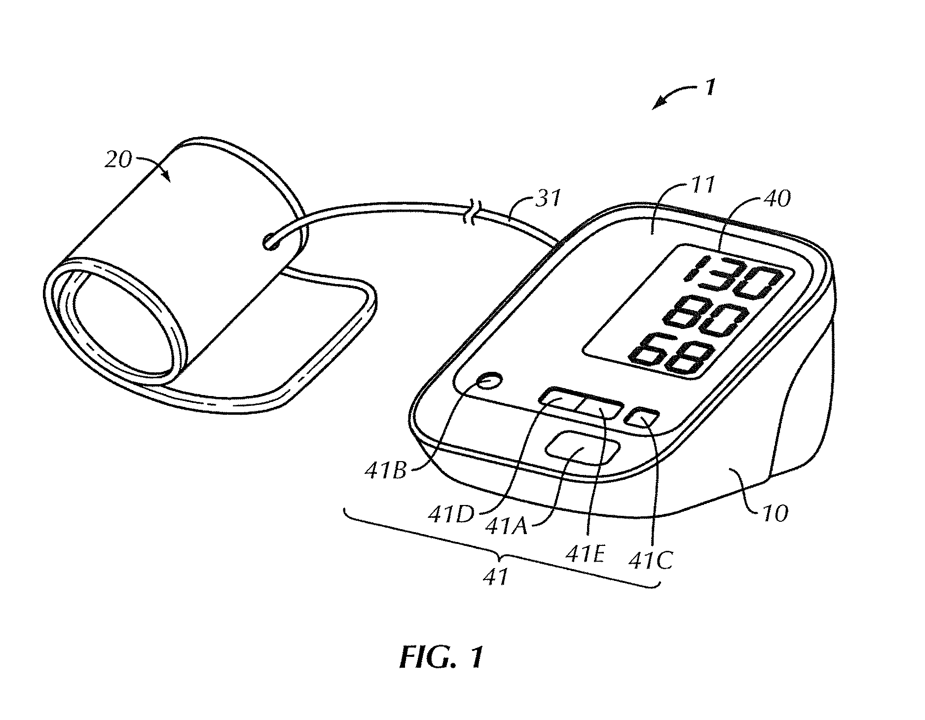
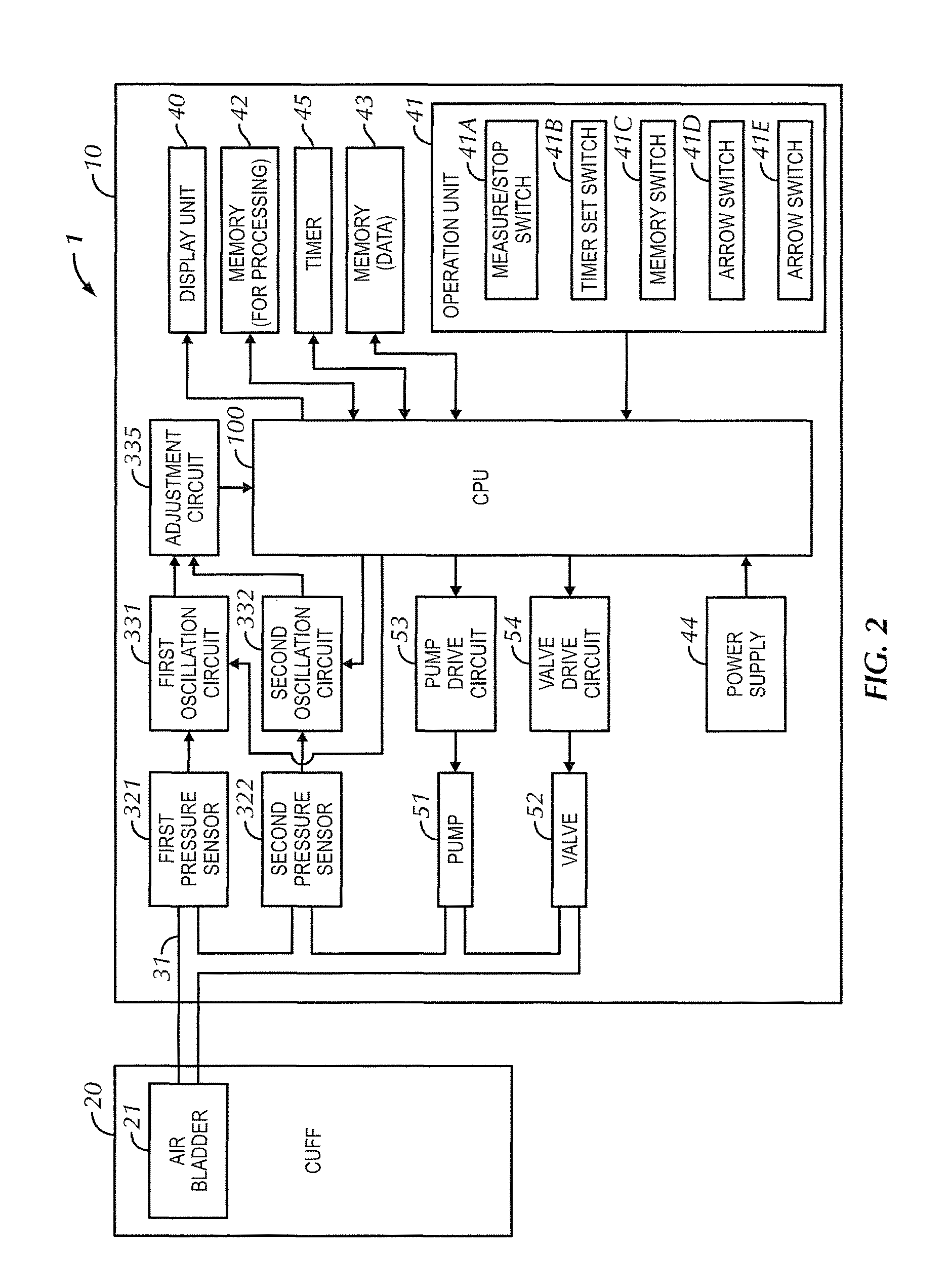
[0040]The present embodiment describes an electronic sphygmomanometer that calculates blood pressures through an oscillometric method using the upper arm as a measurement area, and as an example, includes two p...


PUM


Abstract

A first oscillation circuit and a second oscillation circuit are connected to a first pressure sensor and a second pressure sensor, respectively, and oscillate based on the capacity values of the corresponding pressure sensors. The first oscillation circuit and the second oscillation circuit operate in response to instruction from a CPU. The one of the first oscillation circuit and the second oscillation circuit that has received an activation signal from the CPU outputs a signal having a frequency that corresponds to the capacity value of the corresponding pressure sensor. An adjustment circuit is connected to the first oscillation circuit and the second oscillation circuit, and allows one of the frequency signals to pass therethrough, outputting the signal to the CPU.

Description

TECHNICAL FIELD[0001]This invention relates to electronic sphygmomanometers, and particularly relates to electronic sphygmomanometers that improve the reliability of blood pressure measurement values.BACKGROUND ART[0002]Blood pressure is one index for analyzing cardiovascular disease. Performing a risk analysis for cardiovascular disease based on blood pressure is effective in preventing cardiovascular-related conditions such as stroke, heart failure, and myocardial infarction. In particular, morning hypertension, in which the blood pressure rises in the early morning, is related to heart disease, stroke, and the like.[0003]Furthermore, among morning hypertension symptoms, the symptom called “morning surge”, in which the blood pressure rapidly rises within one hour to one and a half hours after waking up, has been found to have a causal relationship with stroke. Accordingly, understanding the interrelationship between time (lifestyle) and changes in blood pressure is useful in risk ...

Claims


Application Information

Patent Timeline
Patent Type & Authority Patents(United States)
IPC IPC(8): A61B5/02A61B5/022
CPCA61B5/022A61B5/02225
Inventor DOI, RYOSUKENISHIOKA, TAKANORITAKEOKA, KOHEISAWANOI, YUKIYAHORIBATA, KENICHIYANAGASE, MASATAKAHACHIMARU, IZUMI
Owner OMRON HEALTHCARE CO LTD
Learn More