Multiprocessor control apparatus, multiprocessor control method, and multiprocessor control circuit

a control apparatus and control circuit technology, applied in the direction of memory adressing/allocation/relocation, multi-programming arrangements, high-level techniques, etc., can solve the problems of increasing overhead, increasing the required electric power consumption to some extent, and it is difficult to apply a low-power consumption processor architecture to only a processor. achieve the effect of reducing electric power consumption

Active Publication Date: 2010-07-22
GK BRIDGE 1
View PDF13 Cites 81 Cited by
  • Summary
  • Abstract
  • Description
  • Claims
  • Application Information

AI Technical Summary

Benefits of technology

[0016]In view of the above, it is an object of the present invention to provide a multiprocessor control apparatus, a multiprocessor control method, and a multiprocessor control circu

Problems solved by technology

In this arrangement, preparing a large number of (ten or more) low-performance processors only results in increasing the overhead.
Accordingly, even if a load of a program to be executed is reduced, and electric power supply to the processors other than one processor is suspended, since the electric power consumption of the one processor is relatively high, a required electric power consumption is increased to some extent.
For instance, it is difficult to apply a low-power consumption processor architecture to only a processor or processors which should be kept in an operated state.
In this cas

Method used


Image

  • Multiprocessor control apparatus, multiprocessor control method, and multiprocessor control circuit
  • Multiprocessor control apparatus, multiprocessor control method, and multiprocessor control circuit
  • Multiprocessor control apparatus, multiprocessor control method, and multiprocessor control circuit

Examples


first embodiment

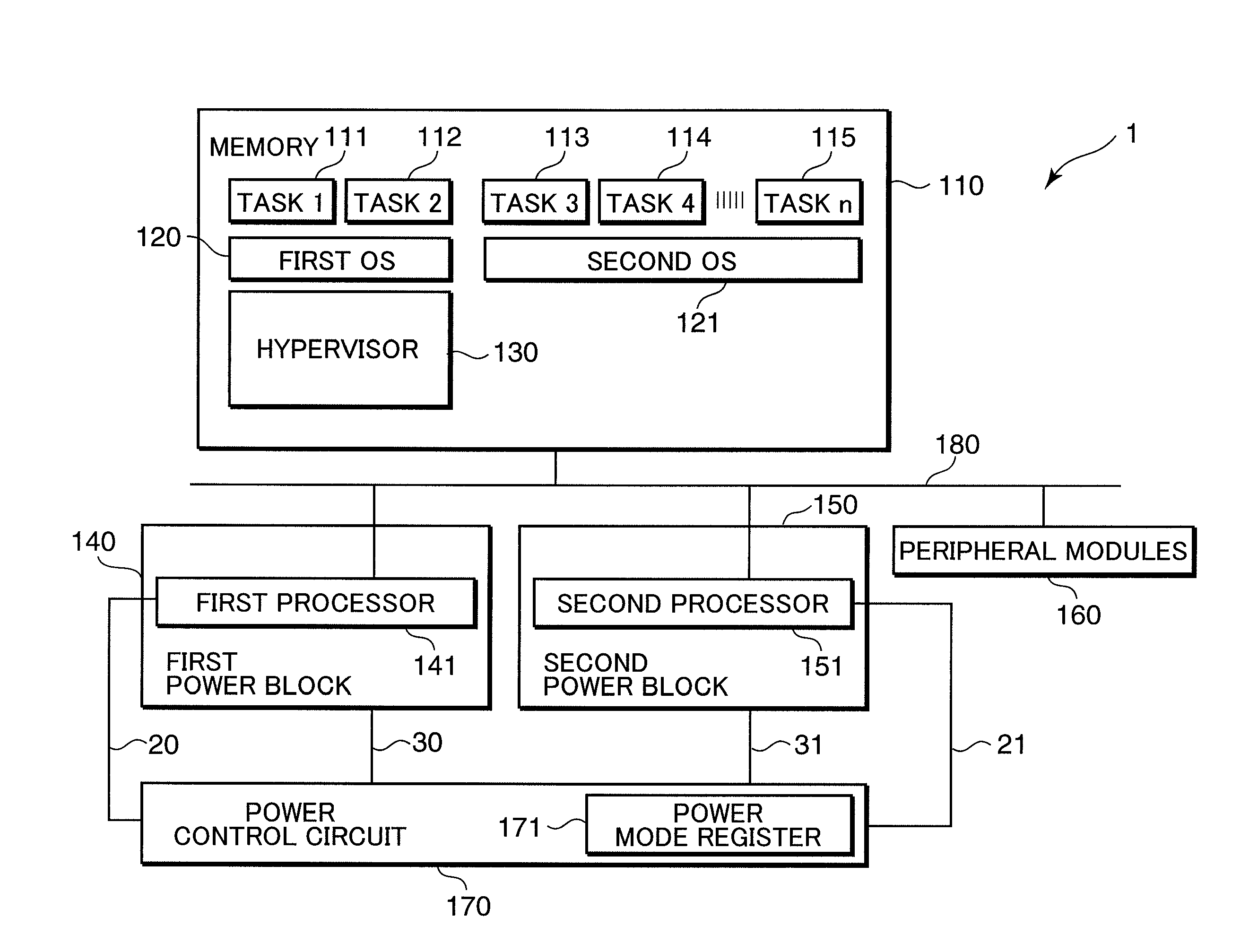
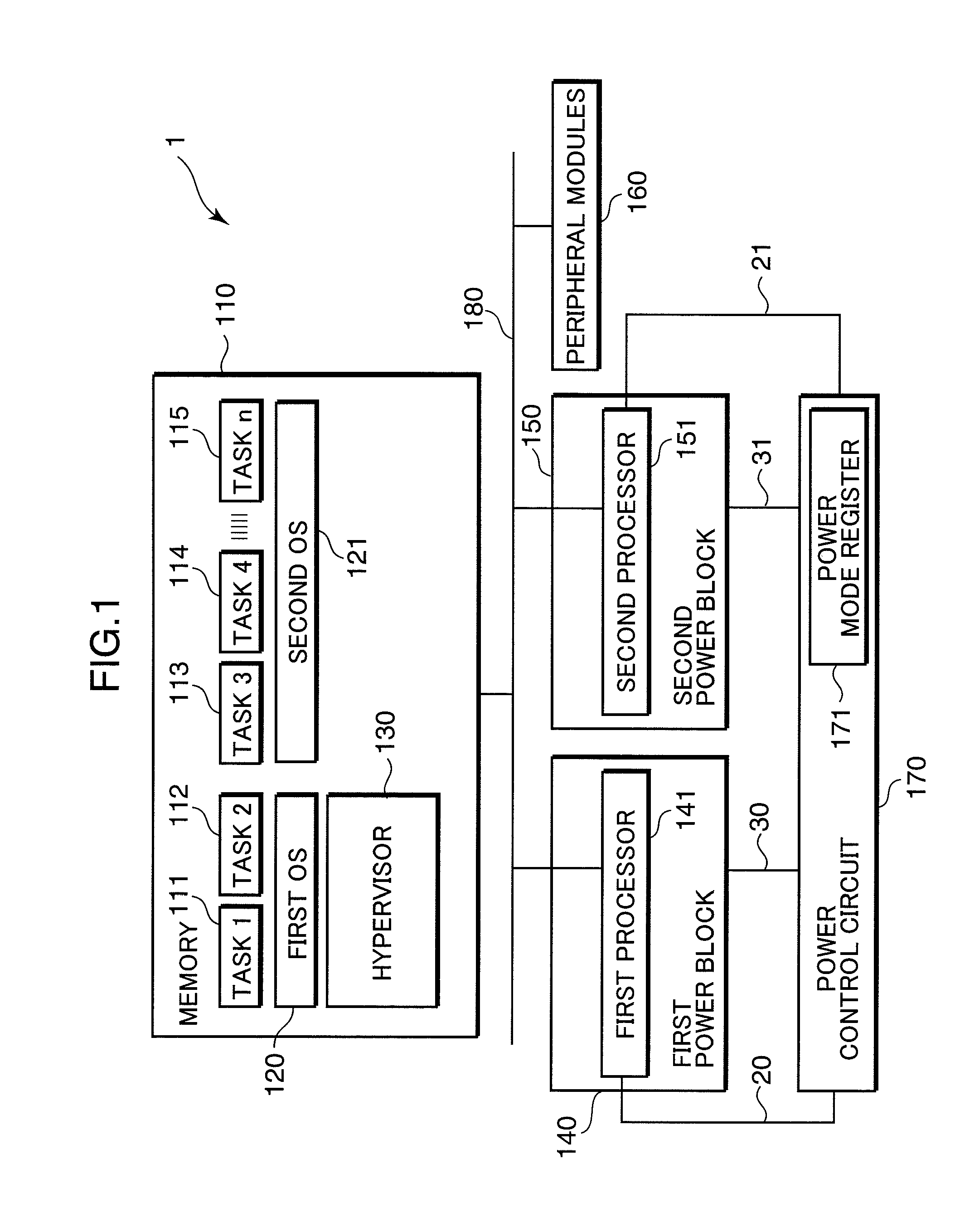
[0043]FIG. 1 is a diagram showing an example of a concrete configuration of a multiprocessor control apparatus (hereinafter, called as a multiprocessor system) in the first embodiment of the invention.

[0044]Referring to FIG. 1, the multiprocessor system 1 in this embodiment includes an internal bus 180, a memory 110 to be connected to the internal bus 180, a first processor 141 which executes an instruction code stored in the memory 110, a second processor 151 which executes an instruction code stored in the memory 110, a power control circuit 170, and peripheral modules 160 to be connected to the internal bus 180.

[0045]In this embodiment, the first processor 141 is a processor (hereinafter, called as a “low-power consumption processor”) having a lower performance and a smaller electric power consumption than those of the second processor 151. The second processor 151 is a processor (hereinafter, called as a “high-performance processor”) having a higher performance and a larger elec...

second embodiment

[0115]FIG. 7 is a diagram showing an example of a configuration of a multiprocessor system in the second embodiment. Referring to FIG. 7, constituent elements having the same reference numerals as those in FIGS. 1 and 6 are constituent elements substantially identical or equivalent to those in FIGS. 1 and 6, and detailed description thereof is omitted herein.

[0116]Referring to FIG. 7, the multiprocessor system 3 in the second embodiment includes an internal bus 180, a memory 110, a first processor 141, a first cache memory 142, a second processor 151, a second cache memory 152, a power control circuit 170, and peripheral modules 160.

[0117]The multiprocessor system 3 in this embodiment has a feature that the power control circuit 170 is configured to control electric power supply to each of the low-power consumption processor 141, the high-performance processor 151, the first cache memory 142, and the second cache memory 152.

[0118]In the second embodiment shown in FIG. 7, the power b...

third embodiment

[0153]In the foregoing embodiments of the invention, the low electric power consumption technology mainly using processors has been described. Generally, however, it is necessary to realize the low electric power consumption technology including a memory and peripheral modules. For instance, in an ordinary multiprocessor system and multi-core LSI, normally, peripheral modules are correlated to individual processors by one-to-one correspondence in terms of hardware or at initialization; or notify a result such as an interruption to a processor which has conducted a process request.

[0154]However, in the foregoing embodiments, if there is a correlation between a processor and peripheral modules which perform e.g. an interruption, an unintended processor may be operated at a timing such as an interruption, which may fail to realize an intended low electric power consumption technology.

[0155]As described above, in the conventional multiprocessor system, it is often the case that individu...


PUM


Abstract

An object of the invention is to reduce the electric power consumption resulting from temporarily activating a processor requiring a large electric power consumption, out of a plurality of processors. A multiprocessor system (1) includes: a first processor (141) which executes a first instruction code; a second processor (151) which executes a second instruction code, a hypervisor (130) which converts the second instruction code into an instruction code executable by the first processor (141); and a power control circuit (170) which controls the operation of at least one of the first processor (141) and the second processor (151). When the operation of the second processor (151) is suppressed by the power control circuit (170), the hypervisor (130) converts the second instruction code into the instruction code executable by the first processor (141), and the first processor (141) executes the converted instruction code.

Description

TECHNICAL FIELD[0001]The present invention relates to a multiprocessor control apparatus, a multiprocessor control method, and a multiprocessor control circuit for controlling a plurality of processors sharing a memory and an internal bus, and more particularly to a multiprocessor system including a plurality of processors sharing a memory, a system LSI (Large Scale Integration) including a plurality of processor cores sharing an internal bus, a multiprocessor control apparatus, a multiprocessor control method, and a multiprocessor control circuit for controlling an electric power to be supplied to processors in these systems.BACKGROUND ART[0002]Multitudes of multiprocessor systems including a plurality of processors sharing a memory have been applied in various industrial fields. As a recent technical trend of system LSI, there is actively used a multi-core architecture loaded with a plurality of processor cores. Particularly, in an embedded system LSI, it is often advantageous to ...

Claims


Application Information

Patent Timeline
IPC IPC(8): G06F9/318G06F1/32G06F12/08
CPCG06F1/3203Y02D50/20G06F1/329G06F1/3293G06F9/45533G06F9/52G06F12/0831G06F12/0864G06F2212/1028Y02D10/122Y02D10/13Y02D10/171Y02D10/24Y02D10/26Y02D10/28G06F1/3287Y02D10/00Y02D30/50
Inventor SAITO, MASAHIKOMIZUYAMA, MASASHIGE
Owner GK BRIDGE 1
Why Eureka
Try Eureka