Tubular fiber membrane with nanoporous skin

a fiber membrane and nanoporous skin technology, applied in the field of tubular fiber membranes, can solve the problems of reducing performance, clogging pores, and reducing performance over time, and reducing performance. the effect of clogging pores

Inactive Publication Date: 2013-08-15
AGENCY FOR SCI TECH & RES
View PDF7 Cites 5 Cited by
  • Summary
  • Abstract
  • Description
  • Claims
  • Application Information

AI Technical Summary

Benefits of technology

[0007]It has been realized that fiber membranes suitable for hemofiltration or hemodialysis may not be suitable for reabsorption or for use as artificial renal proximal tubules. In particular, when the pore sizes in fiber membranes used in reabsorption

Problems solved by technology

It has been realized that fiber membranes suitable for hemofiltration or hemodialysis may not be suitable for reabsorption or for use as artificial renal proximal tubules.
In particular, when the pore sizes in fiber membranes used in reabsorption processes are larger near the outer surface than near the inner (lumen) surface of the fiber membranes, some materials, such as health

Method used


Image

  • Tubular fiber membrane with nanoporous skin
  • Tubular fiber membrane with nanoporous skin
  • Tubular fiber membrane with nanoporous skin

Examples


example ia

Preparation of Sample Hollow Fiber Membranes with Oil

[0119]Polyethersulfone (PES, average molecular weight (MW)=51 kDa, BASF™) and polyvinylpyrrolidone (PVP, average MW=25 kDa, Merck™) were slowly added to N-methyl-2-pyrrolidone (NMP) in a glass bottle. The concentrations of PES, PVP, and NMP for different samples are listed in Table I. The mixture was stirred until a homogeneous solution (referred to as the dope solution) was obtained. The dope solution was used to in an extrusion process to form the tubular fiber body, as further described below.

TABLE IContents of Dope Solution (wt %) for Different Fiber SamplesSamplePESPVPNMPS118874S2181072S3161074S420872

[0120]A core solution was prepared using a biocompatible oil, FC3283 (3M™). FC3283 oil is immiscible with water and NMP, and has a density of 1820 kg / m3 and a viscosity of 1.4 cp. The core solution was used in the extrusion process to occupy the lumen space, as further described below.

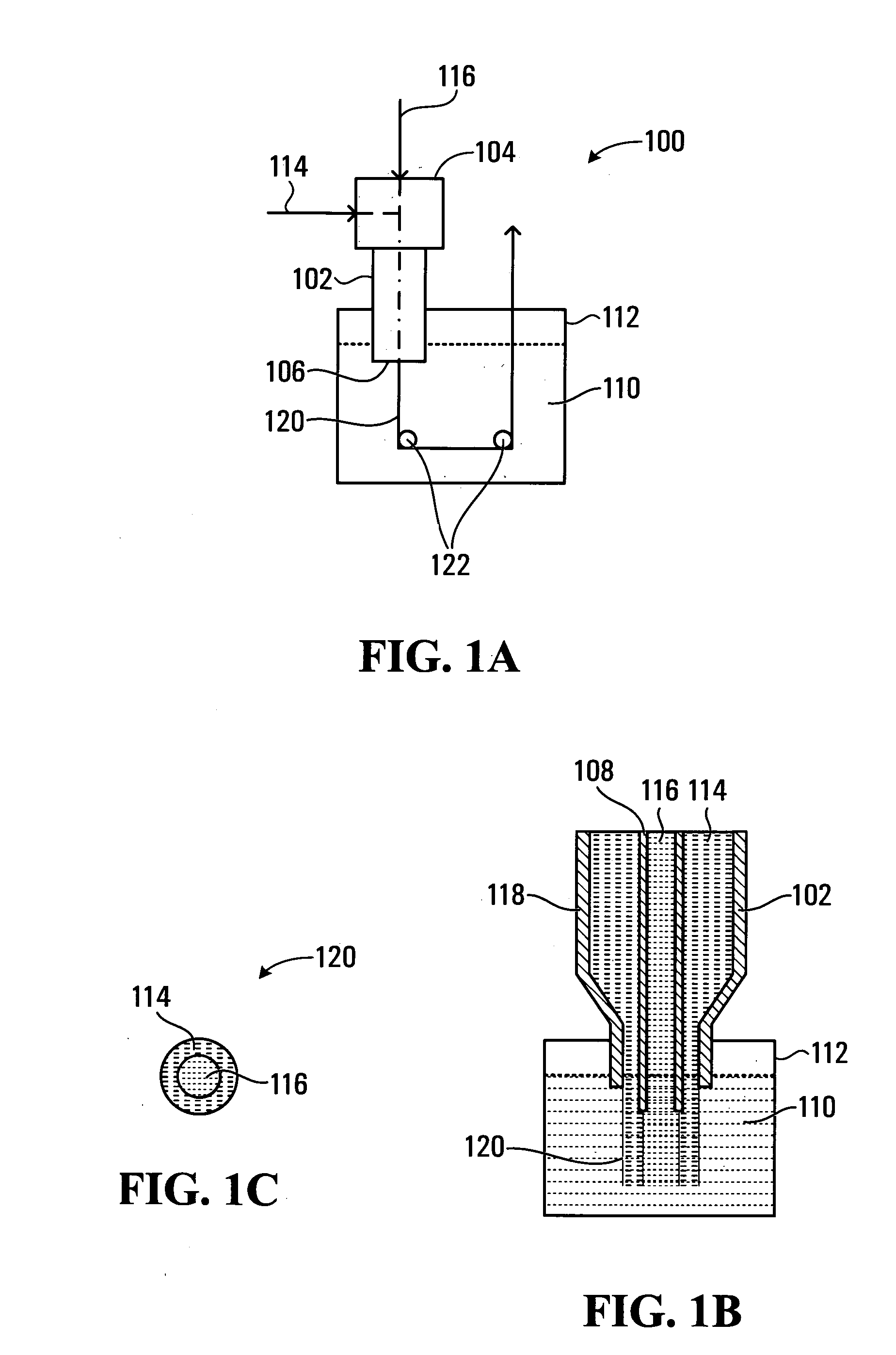
[0121]The extrusion procedure was as describe...

example ib

Sample Filtration Fiber Membrane (Comparison)

[0139]For comparison purposes, sample filtration fibers were fabricated using a conventional dry-wet-spinning process, with the same extruder as used in Example IA. The dope solution and the coagulation bath were prepared and the extrusion procedure was performed similarly as described in Example IA, with the changes noted below. In particular, the dope solution had 18 wt % of PES and 10 wt % of PVP in NMP. The dope solution was injected into the extruder at a flow rate of 0.2 ml / min was used. The core solution was formed of 10 vol % of NMP in water, and was injected into the extruder at a flow rate of 0.3 ml / min. The extruder exit was placed 10 mm above the primary coagulation bath.

[0140]FIGS. 5A, 5B, 5C and 5D show SEM images of a comparison filtration fiber membrane made according to the above procedure.

[0141]As compared to the sample fibers in Example IA, the sample fibers of Example IB had a different pore structure and pore size dis...

example ii

Preparation of Sample Hollow Fiber Membranes with Water / NMP Mixture as Core Solution

[0142]Sample fiber membranes were prepared according to the procedure of Example I, except that the core solution was a mixture of water and NMP.

[0143]An advantage of using H2O / NMP mixture of the core solution is that after the fiber membrane was formed, the core solution may be conveniently removed from the lumen through the membrane pores, such as by diffusion. In comparison, when oil is used as the core solution, the oil in the lumen was flushed out with water after the fiber membrane had been formed, as oil was immiscible with water or NMP.

[0144]Another advantage of using H2O / NMP mixture as the core solution is that the pore sizes on the inner surface of the fiber membrane can be conveniently tuned by varying the volume fraction of NMP in the core solution.

[0145]Test samples were formed with various NMP concentrations in the core solutions. The NMP concentration was varied from about 60 v % to 90...


PUM

PropertyMeasurementUnit
Pore sizeaaaaaaaaaa
Pore sizeaaaaaaaaaa
Fractionaaaaaaaaaa

Abstract

A wet spinning process for forming a tubular fiber membrane is provided. The tubular fiber membrane has a nanoporous skin layer and a microporous lumen layer. The skin layer defines an outer surface of the fiber membrane and the lumen layer defines a lumen surface of the fiber membrane. The pores in the skin layer may have an average pore size of less than about 7 nm, and pores in the lumen layer may have an average pore size of from about 0.5 to about 3 μm. The fiber membranes may be used in artificial renal proximal tubules, artificial kidneys, bioreactors, or fiber cartridges.

Description

FIELD OF THE INVENTION[0001]The present invention relates generally to tubular fiber membranes, and particularly to fiber membranes for use in artificial renal proximal tubules, artificial kidneys, and bioreactors, and related methods and processes.BACKGROUND OF THE INVENTION[0002]Artificial renal tubule can be used in renal substitution therapy. For example, bioartificial renal tubule assist devices (RAD) have been developed and tested, which utilizes hemodialysis hollow fiber membranes. Generally, these fiber membranes are suitable for hemofiltration or hemodialysis.[0003]An asymmetrical microporous hollow fiber for hemodialysis is described in U.S. Pat. No. 4,906,375 to Heilmann, issued Mar. 6, 1990 (referred to herein as “Heilmann”). The fiber has an inner barrier layer and an outer foam-like supporting structure, and is formed of a hydrophobic organic polymer. The hydrophobic organic polymer may be polysulfones such as polyethersulfones (PES). The outer supporting structure is ...

Claims


Application Information

Patent Timeline
IPC IPC(8): B01D63/02D01D5/06D01D5/247
CPCB01D63/02B01D67/0088B01D69/085B01D69/087A61M1/3689D01D5/06D01D5/247A61M1/1621B01D2313/44B01D63/06A61M1/1625B01D71/68
Inventor YING, JACKIE Y.DENG, RENSHENGHU, MINNI, MING
Owner AGENCY FOR SCI TECH & RES
Why Eureka
Try Eureka