Rolling bearing with seal

a technology of rolling bearing and sealing, which is applied in the direction of engine components, mechanical equipment, machines/engines, etc., can solve the problems of grease inside the bearing from flowing out, and achieve the effect of favorable sealing function and simple structur

Active Publication Date: 2013-10-24
HITACHI ASTEMO LTD +1
View PDF14 Cites 2 Cited by
  • Summary
  • Abstract
  • Description
  • Claims
  • Application Information

AI Technical Summary

Benefits of technology

[0006]The present invention has been made in view of the above-described circumstances, and an object of the present invention is to provide the rolling bearing with seal with a simple structure including a seal member which is capable of making a sealing pressure of a seal lip against an inner race higher than ...

Problems solved by technology

This weakens a sealing pressure of the seal lip against the inn...

Method used


Image

  • Rolling bearing with seal
  • Rolling bearing with seal
  • Rolling bearing with seal

Examples


first embodiment

[0032]Next, operation of the first embodiment will be described.

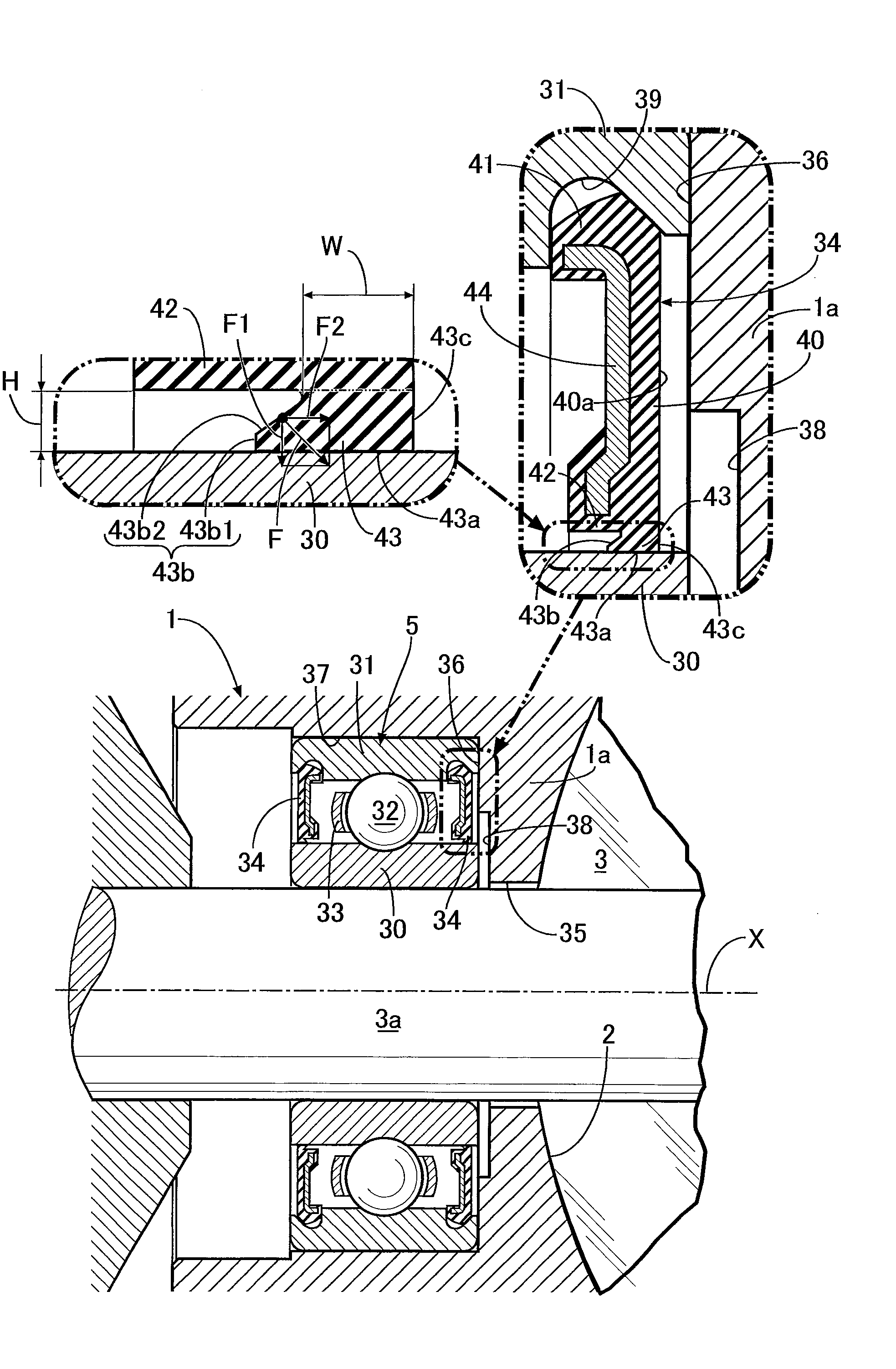
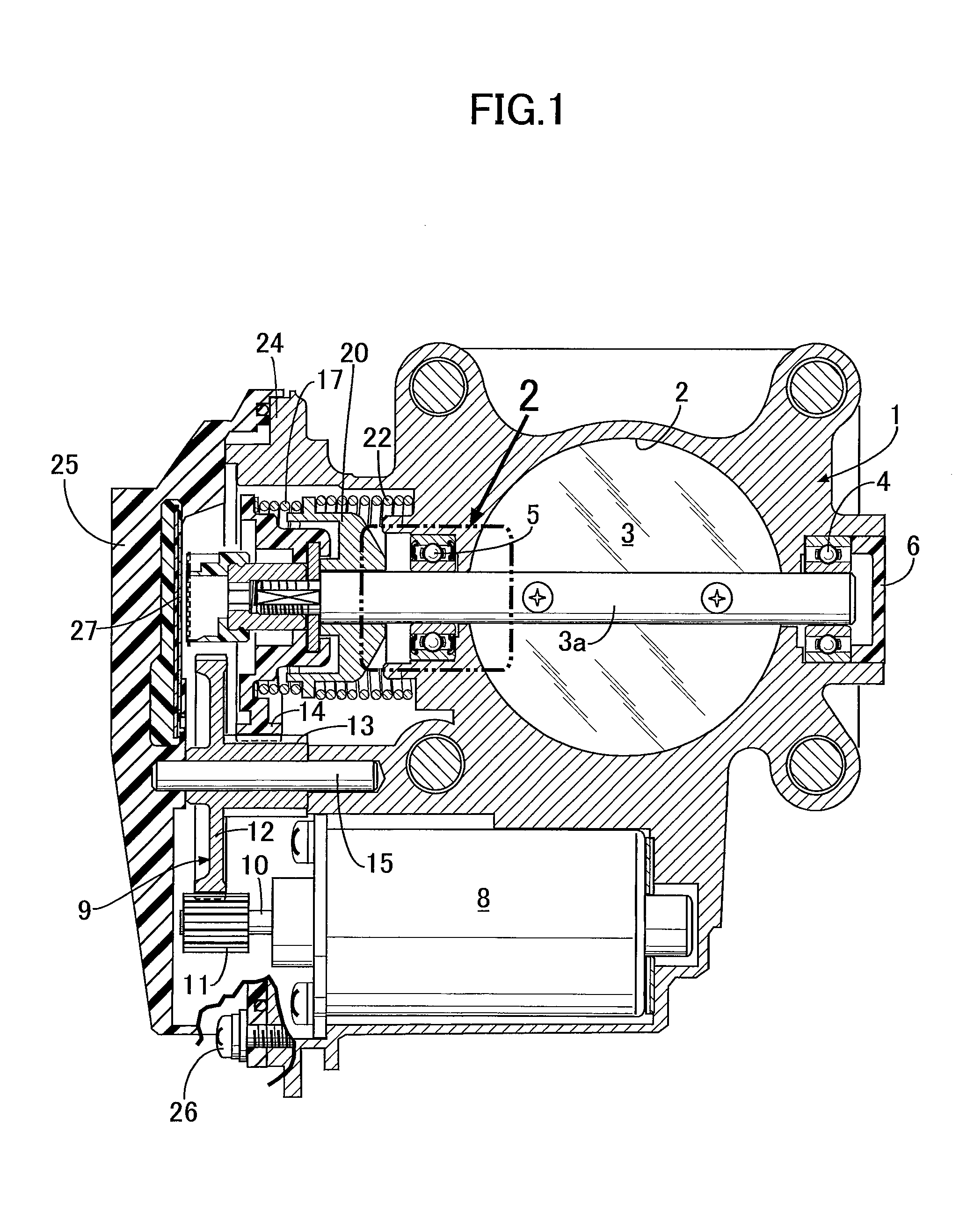
[0033]During the operation of the engine, the throttle valve 3 is driven by the electric motor 8 through the reduction gear mechanism 9 to open and close the intake passage 2, thereby controlling the amount of intake air of the engine. At this time, since the valve stem 3a of the throttle valve 3 is rotatably supported by the pair of left and right rolling bearings 4 and 5, the rotation of the valve stem 3a, that is, the opening and closing operation of the throttle valve 3 can be smoothly performed. Moreover, since the rolling bearing 5 on the control case 24 side, in particular, includes the pair of seal members 34 covering opposite sides of the group of the balls 32, the rolling bearing 5 is capable of preventing pressure shift between the intake passage 2 and the control case 24, and preventing the grease inside the rolling bearing 5 with seal from flowing out.

[0034]Meanwhile, during the operation of the engine, a p...

second embodiment

[0038]Next, the present invention, which is shown in FIG. 3, will be described.

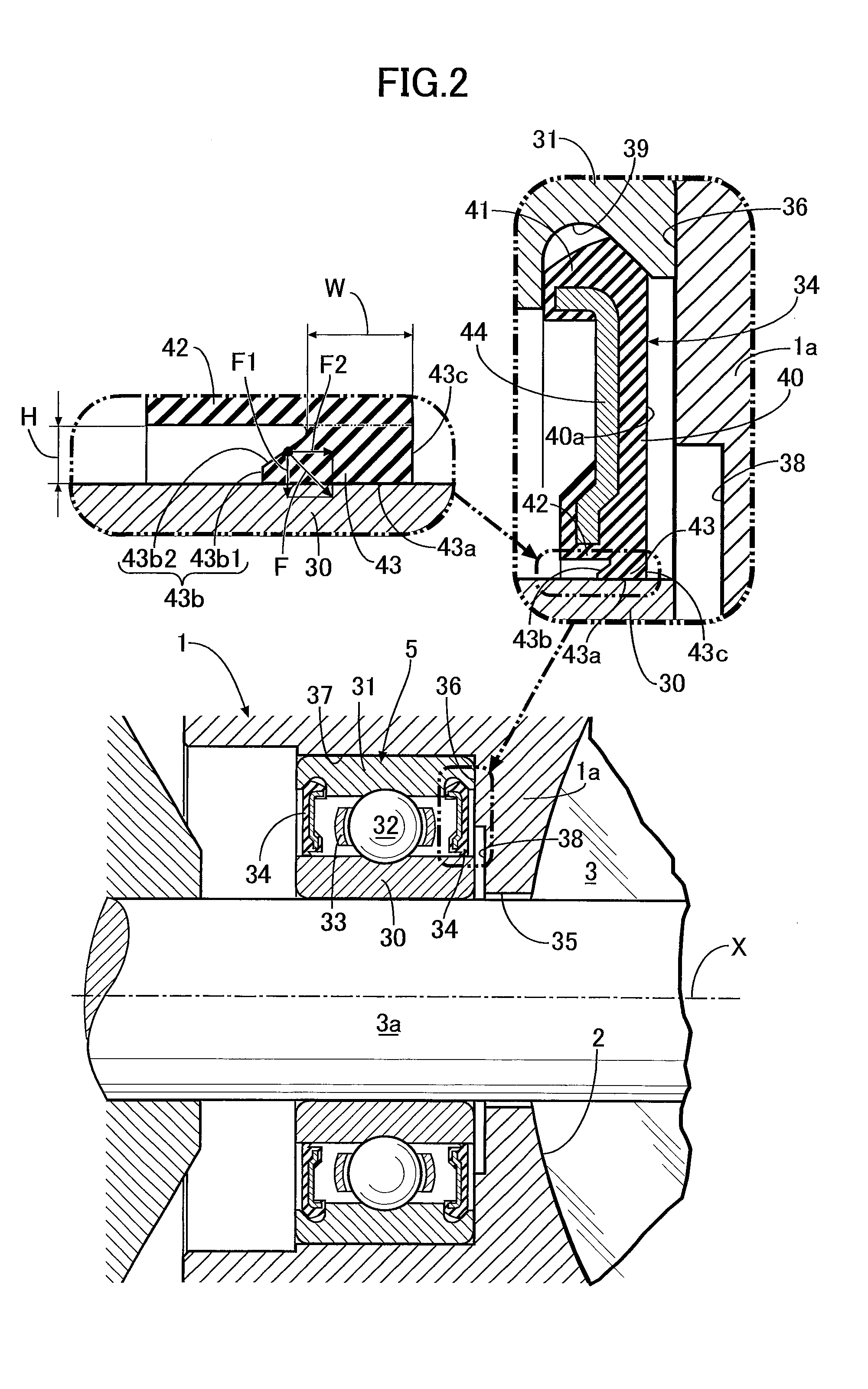
[0039]In the second embodiment, an annular recess portion 45 recessed to immediately above the seal lip 43 is formed in an outer side surface of the lip supporting portion 42 in the seal member 34. The other configurations are the same as those of the aforementioned embodiment, and the portions corresponding to those of the aforementioned embodiment are denoted by the same reference numerals in FIG. 3, and the same description will be omitted.

[0040]According to the second embodiment, the supporting stiffness of the lip supporting portion 42 for the seal lip 43 can be appropriately reduced by the depth of the recess portion 45, making it possible to adjust a friction torque between the seal lip 43 and the inner race 30. Therefore, a change in an allowable rotational torque of the valve stem 3a, that is, an allowable rotational torque of the inner race 30 press-fitted and coupled to the valve stem 3a, can b...


PUM


Abstract

A seal lip having: a cylindrical seal surface in close contact with an outer peripheral surface of an inner race with outer side and inner side surfaces standing upright respectively from an outer end and an inner end of the seal surface and reaching a lip supporting portion of a seal member, and protruding on an inner peripheral surface of the lip supporting portion. The outer side surface is a perpendicular surface standing upright from the outer end of the seal surface in a direction perpendicular to a generating line of the outer peripheral surface of the inner race. The inner side surface includes: a perpendicular surface standing upright from the inner end of the seal surface in parallel with the outer side surface; and a conical surface inclined toward the outer side surface extending outward in a radial direction from an outer peripheral end of the perpendicular surface.

Description

BACKGROUND OF THE INVENTION[0001]1. Field of the Invention[0002]The present invention relates to an improvement of a rolling bearing with seal comprising: an inner race; an outer race surrounding the inner race; a plurality of rolling members arranged circumferentially and interposed between the inner and outer races; and a pair of annular seal members disposed between the inner and outer races in such a manner as to cover opposite sides of the rolling members, wherein an attachment bead to be fixed to the outer race is formed on an outer periphery of each of the seal members, and a seal lip rotatably and slidably being in close contact with an outer peripheral surface of the inner race is formed on an inner periphery of each of the seal members.[0003]2. Description of the Related Art[0004]Such a rolling bearing with seal is, as disclosed in Japanese Patent Application Laid-open No. 2004-263734, interposed between a partition wall, between two chambers having different internal pres...

Claims


Application Information

Patent Timeline
IPC IPC(8): F16C33/76F16C19/06F16C33/66F16C33/78
CPCF16C33/76F16C33/7856F16C33/7823F16C19/06F16C2361/91F16C2360/22F02D9/106F16K1/2268F16J15/164F16J15/322F16K1/224
Inventor OHBA, TOMOAKIUSAMI, TAKUYANISHIMURA, KENICHIROFURUKOSHI, AKIMI
Owner HITACHI ASTEMO LTD
Why Eureka
Try Eureka