
Power generator integrated with bearing
- Summary
- Abstract
- Description
- Claims
- Application Information
AI Technical Summary
Benefits of technology
Problems solved by technology
Method used
Image

Examples
Embodiment Construction
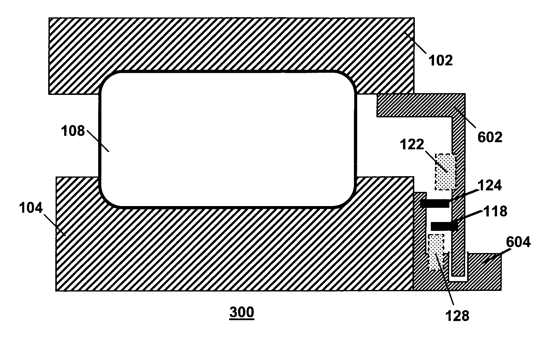
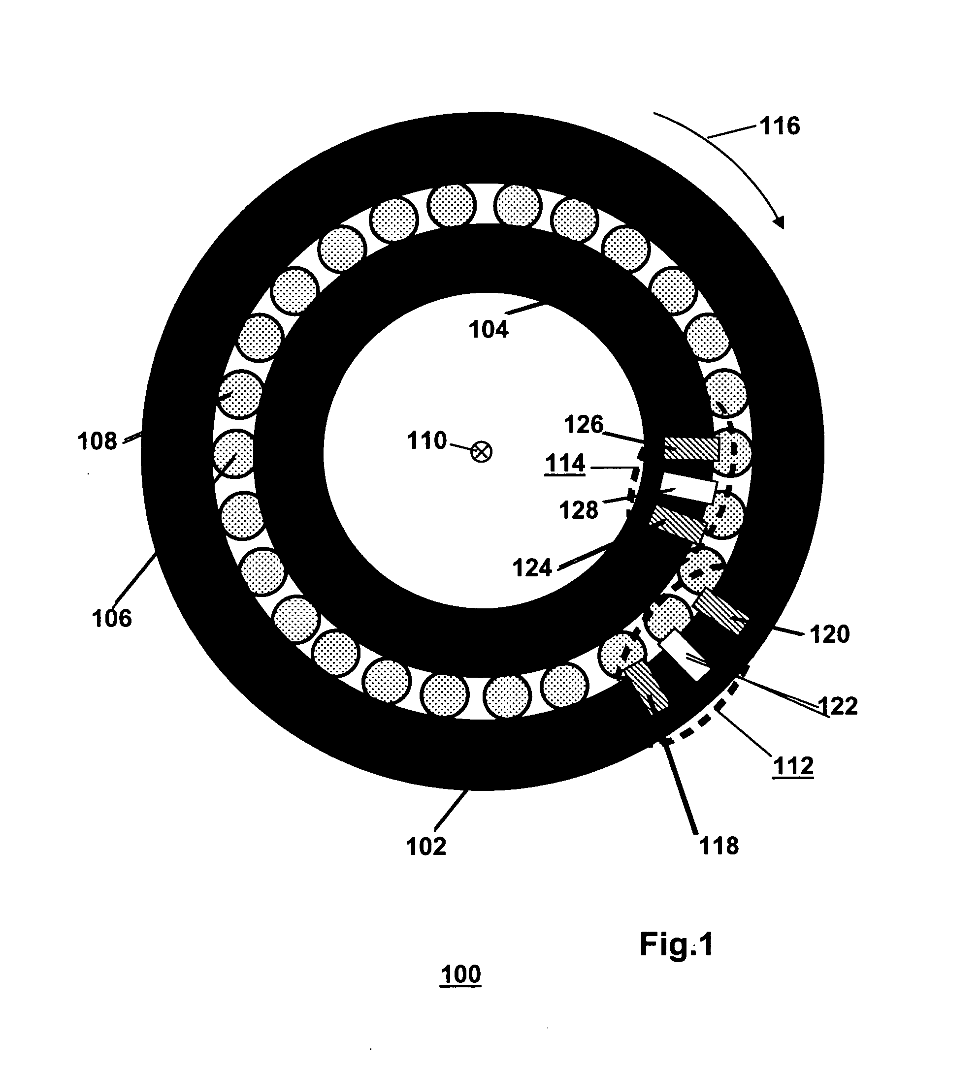
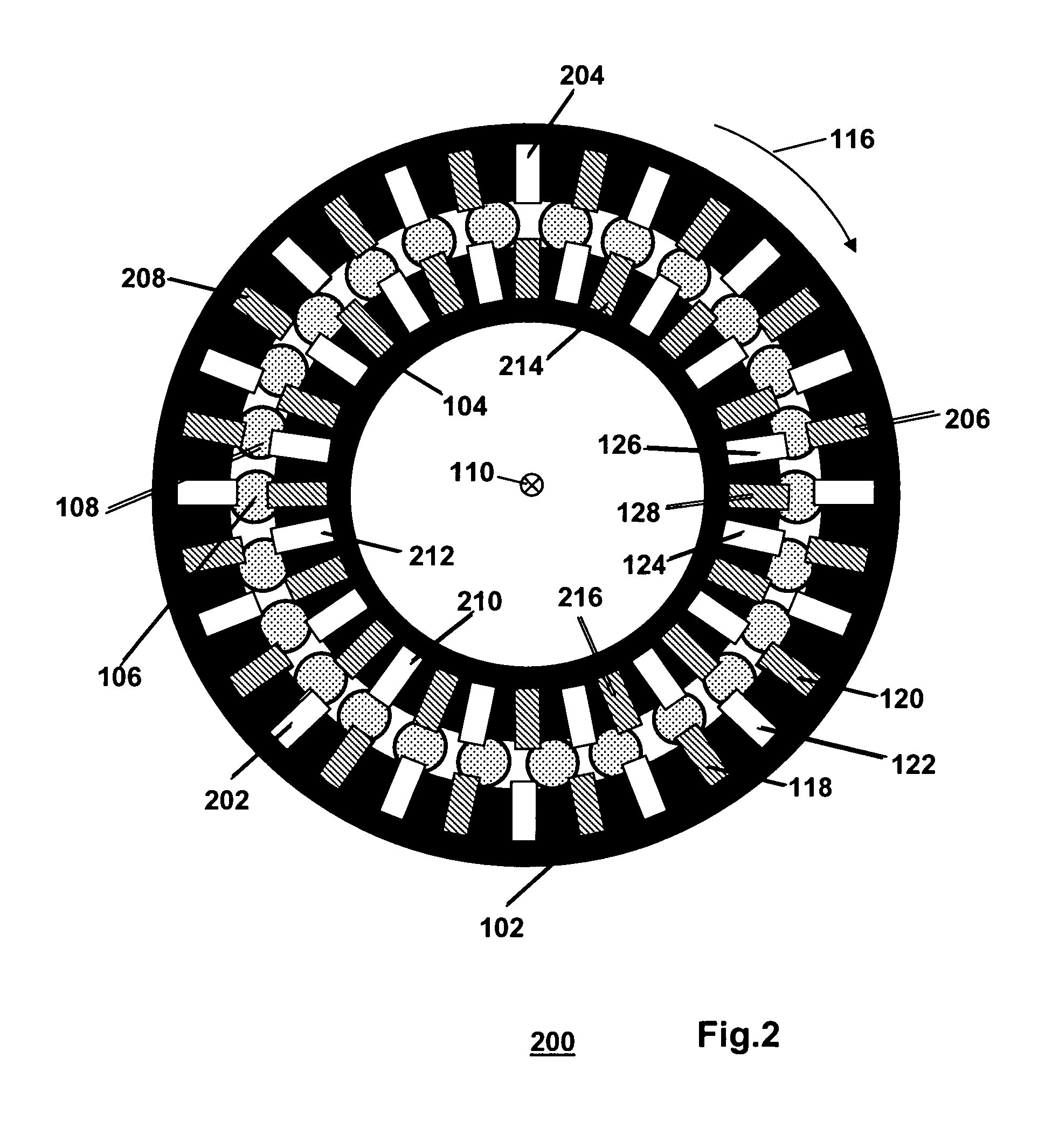
[0033]FIG. 1 is a diagram illustrating a first bearing 100 with components for implementing a generator for generating electric power in operational use of the first bearing 100. The first bearing 100 is a rolling element bearing comprising a first ring 102, a second ring 104 and a plurality of rolling elements positioned between the first ring 102 and the second ring 104. In order to not obscure the drawing, only a first one and a second one of the rolling elements are indicated with reference numerals 106 and 108, respectively. The first ring 102 and the second ring 104 are arranged for coaxial rotation with respect to each other around a common axis 110 in operational use of the first bearing 100. The diagram of Fig.1 shows the first bearing 100 in an orientation, wherein the common axis 110 runs perpendicularly to the plane of the drawing. Accordingly, the diagram shows the first bearing 100 with a first flank of the first ring and a second flank of the second ring 104 facing th...
PUM
 Abstract
Description
Claims
Application Information