Pivot pad brake caliper

Active Publication Date: 2014-05-08
BEIJINGWEST INDUSTRIES
View PDF19 Cites 2 Cited by
  • Summary
  • Abstract
  • Description
  • Claims
  • Application Information

AI Technical Summary

Benefits of technology

The invention improves the way brakes work by adjusting how much they move when the driver squeezes the brakes. This reduces how much brakes when the driver squeezes the brakes. This makes braking smoother and less painful for the driver. It also helps prevent brakes from wearing down too quickly and it reduces the sudden jerking sensation when braking.

Problems solved by technology

However, reducing the stiffness of the caliper assembly can often result in a decrease in brake performance such as increased brake drag, brake pad taper wear, and brake distance.
The decrease in brake performance may translate into vehicle issues such as degraded fuel economy, increased stopping distance, and poor pedal feel.

Method used


Image

  • Pivot pad brake caliper
  • Pivot pad brake caliper
  • Pivot pad brake caliper

Examples


Embodiment Construction

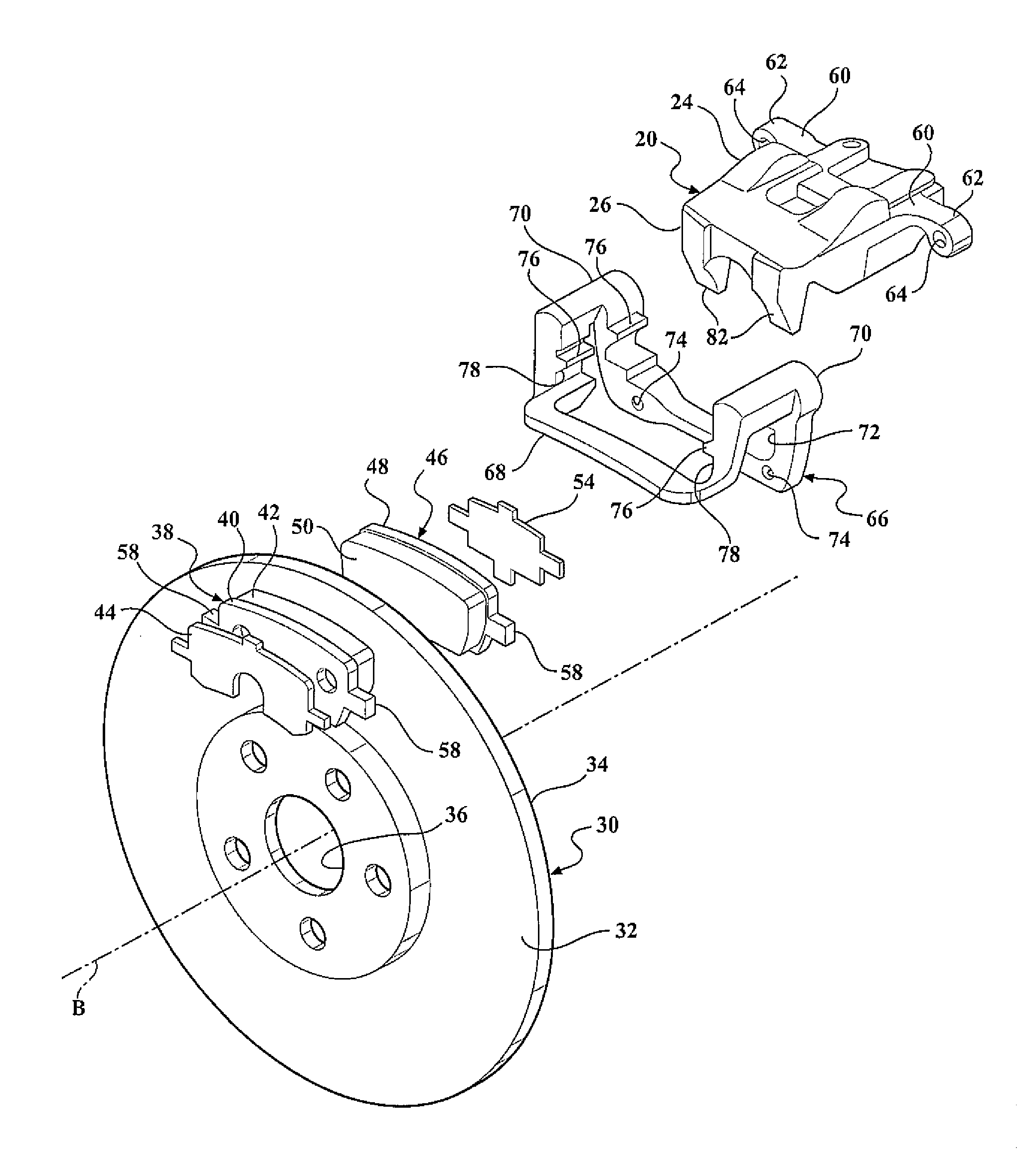
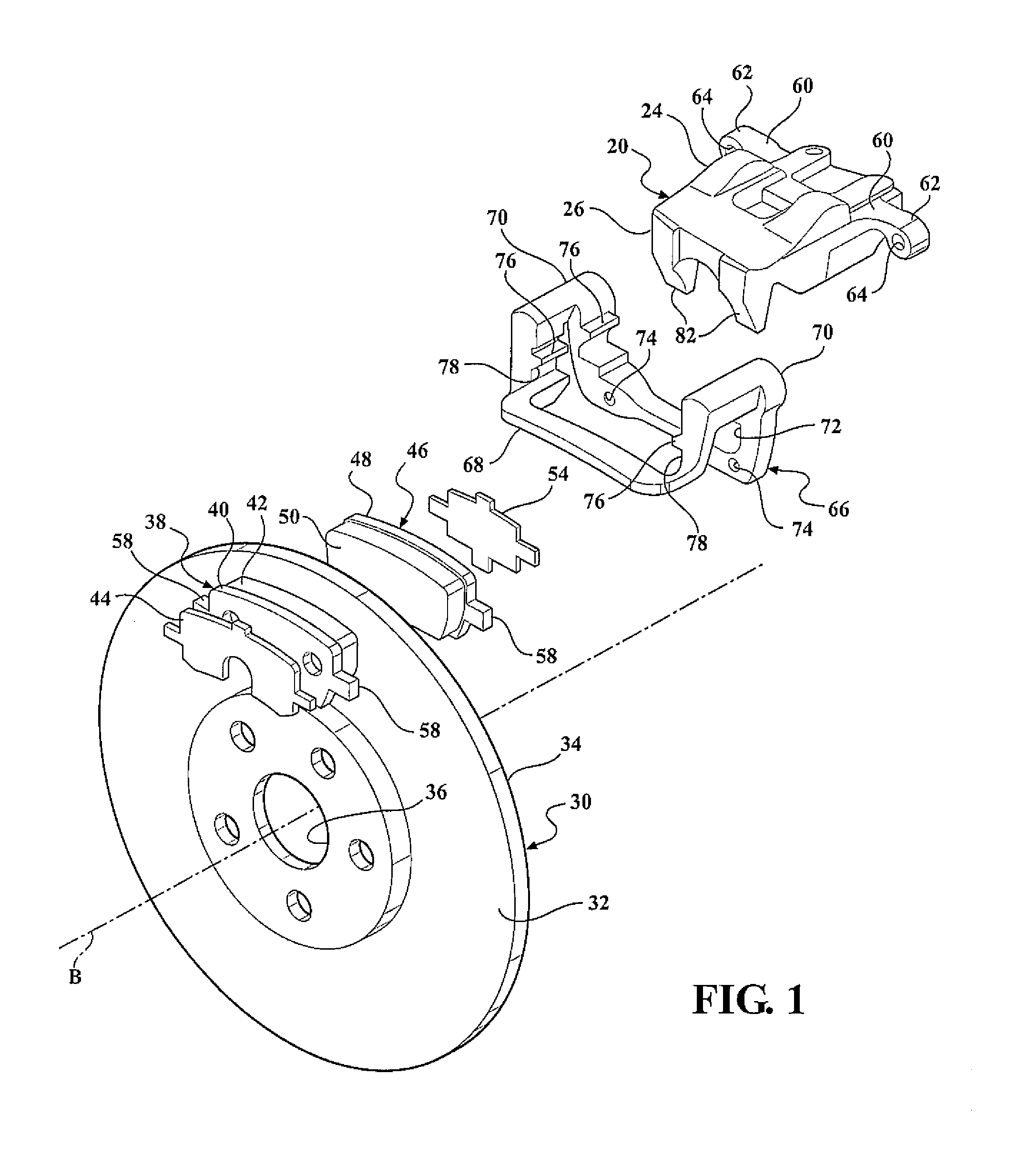
[0021]Referring to the Figures, wherein like numerals indicate corresponding parts throughout the several views, a brake caliper assembly for a vehicle is generally shown in FIG. 1.

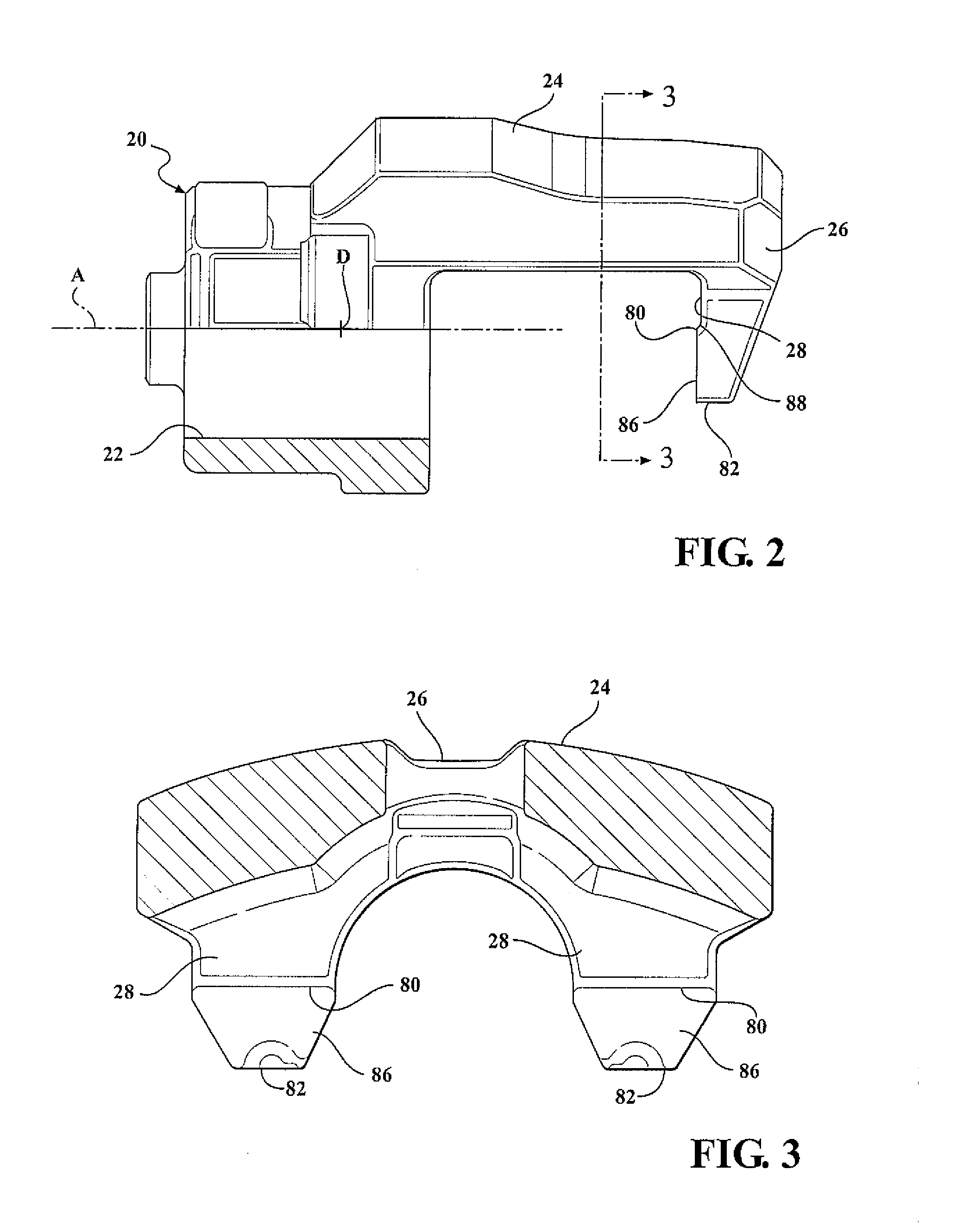
[0022]The assembly includes a caliper housing 20, as generally indicated, including a piston bore 22 having a cylindrical shape disposed horizontally along a first center axis A and a bridge 24 extending between the piston bore 22 and a pair of caliper fingers 26 interconnecting the caliper fingers 26 and the piston bore 22. The caliper fingers 26 of the caliper housing 20 extend downwardly from the bridge 24 in a spaced and parallel relationship to define a fiat surface 28.

[0023]A rotor 30, as generally indicated and having a disc shape defines a first side 32 and a second side 34 for rotation about a second center axis B and disposed adjacent to the caliper fingers 26. The rotor 30 defines a center aperture 36 disposed along the second center axis B extending between the first side 32 of the rotor 30 an...


PUM


Abstract

A caliper housing including a piston bore and a bridge extending between the piston bore and a pair of caliper fingers interconnecting the caliper fingers and the piston bore. The caliper fingers of the caliper housing extend downwardly from the bridge to define a flat surface. A rotor having a disc shape defines a first side and a second side and disposed adjacent to the caliper fingers. An outer brake pad defining a first centroid is disposed adjacent to the first side of the rotor abutting the caliper fingers allowing the caliper fingers to urge the outer brake pad into engagement with the first side of the rotor. Each of the caliper fingers defines a pivot edge extending between the outer brake pad and the flat surface of the caliper fingers allowing the outer brake pad to pivot about the pivot edge.

Description

BACKGROUND OF THE INVENTION[0001]1. Field of the Invention[0002]The present invention relates to a brake caliper assembly for a vehicle.[0003]2. Description of the Prior Art[0004]Such assembly is disclosed in the U.S. Pat. No. 5,036,932 to Schonenberger wherein a caliper housing includes a piston bore of generally cylindrical shape disposed horizontally along a first center axis and a bridge extending between the piston bore and a caliper fingers interconnecting the caliper fingers and the piston bore. The caliper finger extends downwardly from the bridge to define a flat surface. A rotor of generally disc shape defines a first side and a second side for rotation about a second center axis and disposed adjacent to the caliper finger. An outer brake defines a first centroid disposed between the second side of the rotor and the caliper finger.[0005]It has long been recognized that the thickness of the brake disc rotor can vary circumferentially and radially and the rotor thickness var...

Claims


Application Information

Patent Timeline
IPC IPC(8): F16D55/226B60T1/06F16D65/00F16D66/02
CPCF16D55/226F16D66/02F16D65/0068B60T1/065F16D55/2265F16D65/12F16D2121/04F16D55/2262
Inventor HOXIE, STEVEN GLENNREDER, MARTIN JOHN
Owner BEIJINGWEST INDUSTRIES
Why Eureka
Try Eureka