Lock-up device and torque converter

a technology of locking device and torque converter, which is applied in the direction of fluid gearing, mechanical equipment, gearing, etc., can solve the problem of easy deformation of the low spring constant of the spring spring

Active Publication Date: 2020-12-29
FCC KK
View PDF26 Cites 1 Cited by
  • Summary
  • Abstract
  • Description
  • Claims
  • Application Information

AI Technical Summary

Benefits of technology

[0010]According to a feature of the present invention with this structure, in the lock-up device, the damper pressing portions press the center part of the damper spring onto the projecting part of the intermediate member. Therefore, displacement and deformation of the damper spring to the outer side in the radial direction in rotational drive of the clutch piston are prevented. Accordingly, the lock-up device can prevent generation of hysteresis torque by friction between the damper spring and the clutch piston and improve attenuation performance of torque variation of the engine. In particular, in order to efficiently attenuate torque variation of the engine, use of the damper spring with low spring constant is effective. However, the damper spring with low spring constant can be easily deformed to the clutch piston side as well by buckling in contraction. Nevertheless, the lock-up device according to the present invention can effectively prevent deformation of the damper spring with low spring constant to the clutch piston side as well.
[0014]According to another feature of the present invention with this structure, in the lock-up device, the projecting part of the intermediate member projects toward the outer side in the radial direction than the side surface of the inner side of the center part of the damper spring in the same radial direction until the rotational number of the clutch piston reaches at least 1500 rpm (including the rotational number that can be regarded as substantially 1500 rpm even if it is less than 1500 rpm). Therefore, it is possible to improve attenuation performance of torque variation in low rotational range of the engine.
[0018]Specifically, the torque converter preferably includes: a pump impeller rotationally driven by a driving force of an engine; a turbine runner provided to face the pump impeller so as to be rotationally driven; hydraulic oil provided between the pump impeller and the turbine runner; and the lock-up device according to any one of claims 1 to 4. In the torque converter with this structure, the same effect as the lock-up device described above can be expected.

Problems solved by technology

However, the damper spring with low spring constant can be easily deformed to the clutch piston side as well by buckling in contraction.

Method used


Image

  • Lock-up device and torque converter
  • Lock-up device and torque converter
  • Lock-up device and torque converter

Examples


Embodiment Construction

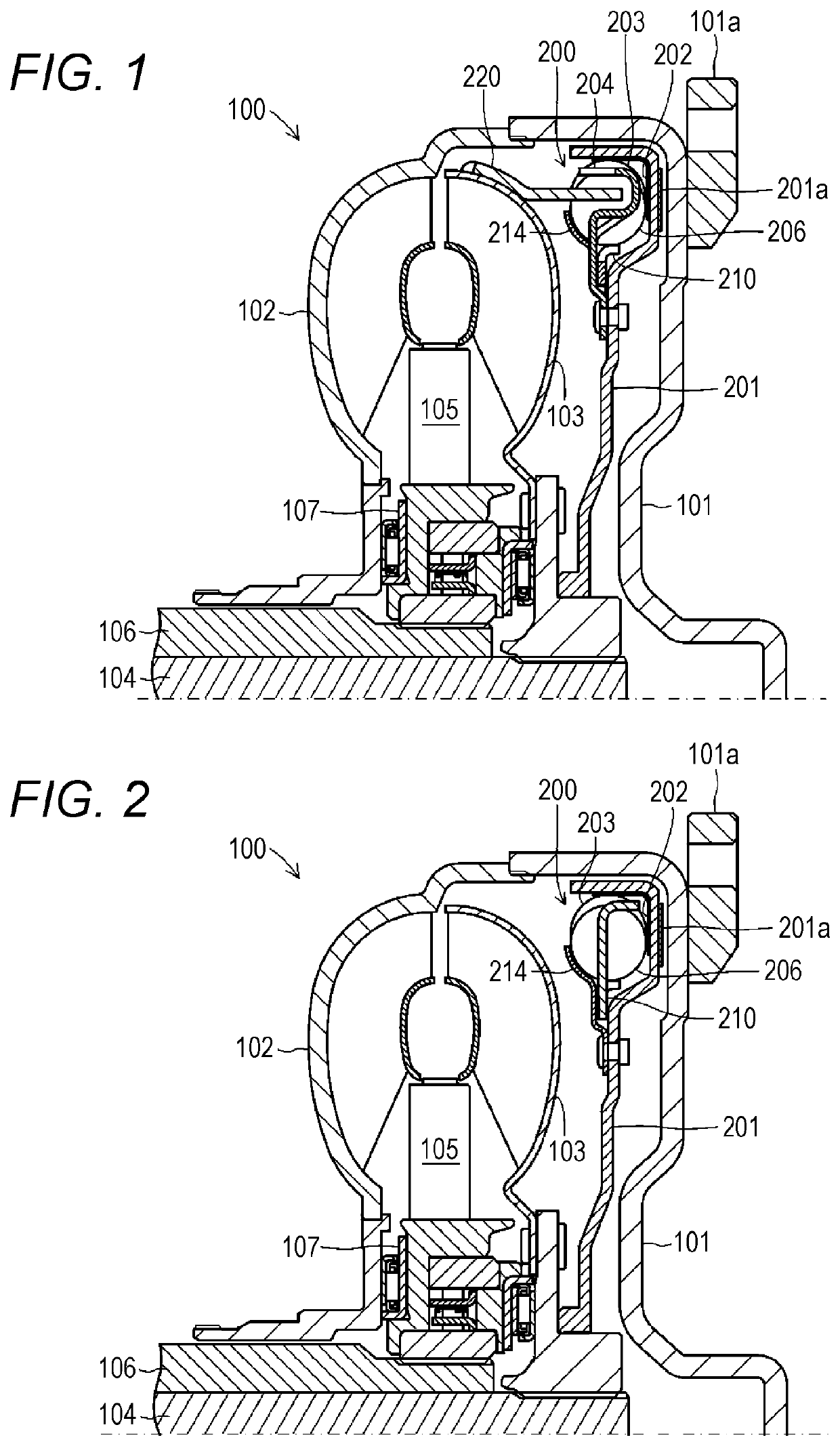
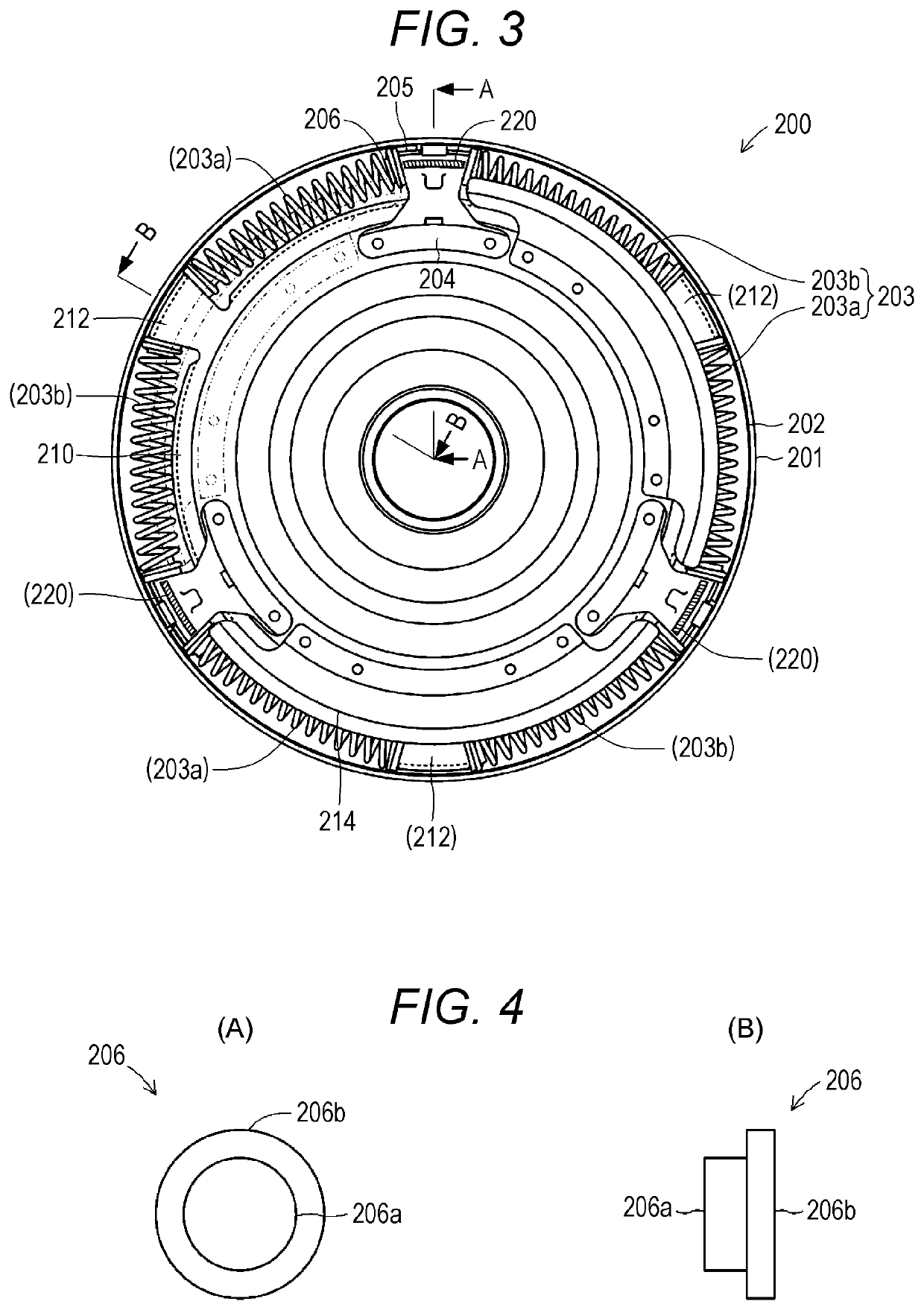
[0028]One embodiment of a lock-up device according to the present invention and a torque converter including the lock-up device will be described below with reference to the drawings. FIG. 1 is a cross-sectional view schematically illustrating a structure of a torque converter 100 including a lock-up device 200 according to the present invention. FIG. 1 corresponds to a cross-sectional view of the torque converter 100 along the line A-A in FIG. 3. FIG. 2 is a cross-sectional view schematically illustrating the structure of the torque converter 100 including the lock-up device 200 according to the present invention in a cross-section different from FIG. 1. FIG. 2 corresponds to a cross-sectional view of the torque converter 100 along the line B-B in FIG. 3. FIG. 3 is a front view of the lock-up device 200 in the torque converter 100 illustrated in FIGS. 1 and 2. The torque converter 100 is mainly a mechanical device provided between an engine and a transmission in an automobile inclu...


PUM


Abstract

A torque converter includes a lock-up device that directly connects a torque converter cover that rotates together with a pump impeller to a turbine runner connected to an output axis. The lock-up device includes a damper spring in a clutch piston that contacts with or moves away from the torque converter cover. In addition, an intermediate member is provided inside the damper spring. A center part of the damper spring is projected toward the inner side of the clutch piston in the radial direction by damper pressing portions and fixed to both ends of the damper spring and a connecting member and pushed onto the projecting part of the intermediate member.

Description

CROSS REFERENCE TO RELATED APPLICATIONS[0001]This application is a national stage application (under 35 U.S.C. § 371) of PCT / JP2014 / 079813, filed Nov. 11, 2014, which claims priority to Japanese Application No. 2013-245828, filed Nov. 28, 2013, the contents of which are incorporated herein by reference in their entireties.TECHNICAL FIELD[0002]The present invention relates to a lock-up device in a torque converter that amplifies a driving force from an engine with hydraulic oil to transmit to an output axis and to a torque converter including the lock-up device.BACKGROUND ART[0003]A torque converter has been mainly provided between an engine and a transmission in a self-propelled vehicle (so-called automatic car) that includes an automatic transmission. A torque converter is a mechanical device that amplifies a driving force from an engine to transmit to an output axis by circulation of hydraulic oil between a pump impeller and a turbine runner that face each other. In the torque con...

Claims


Application Information

Patent Timeline
Patent Type & Authority Patents(United States)
IPC IPC(8): F16H45/02F16F15/123F16D25/0635
CPCF16F15/123F16D25/0635F16H45/02F16H2045/0205F16H2045/0278F16H2045/0221
Inventor FUJIWARA, HIROMIASAI, HIROSHISAIGA, SEIJIENYA, SHOGOSHIMIZU, KATSUHIRO
Owner FCC KK
Why Eureka
Try Eureka