Image projection system and image projection method

Active Publication Date: 2015-01-15
ROLAND DG CORP
View PDF4 Cites 24 Cited by
  • Summary
  • Abstract
  • Description
  • Claims
  • Application Information

AI Technical Summary

Benefits of technology

The present invention provides an image projection system and method that can correct distortion on images projected from multiple image projection sections. The system includes an image-taking section that takes an image of a checkered sheet placed in the image projection region, and a correction section that uses an internal parameter to correct lens-induced distortion of the image. The system can also detect and correct distortion on images projected from different image projection sections, and generate spatial code images with specific code values that change in a lateral or longitudinal direction based on the corrected images. The technical effect of the invention is to provide a more accurate and precise image projection system and method.

Problems solved by technology

As a result, the stereolithography apparatus on which the image projection system is installed is undesirably increased in overall size.
Moreover, when an image projection system is provided with a mechanism for adjusting projector position and / or orientation, fabrication cost for the image projection system is increased.
As a result, fabrication cost for a stereolithography apparatus on which the image projection system is installed is undesirably increased.

Method used


Image

  • Image projection system and image projection method
  • Image projection system and image projection method
  • Image projection system and image projection method

Examples


Embodiment Construction

[0063]Hereinafter, preferred embodiments of an image projection system and an image projection method according to the present invention will be described with reference to the accompanying drawings.

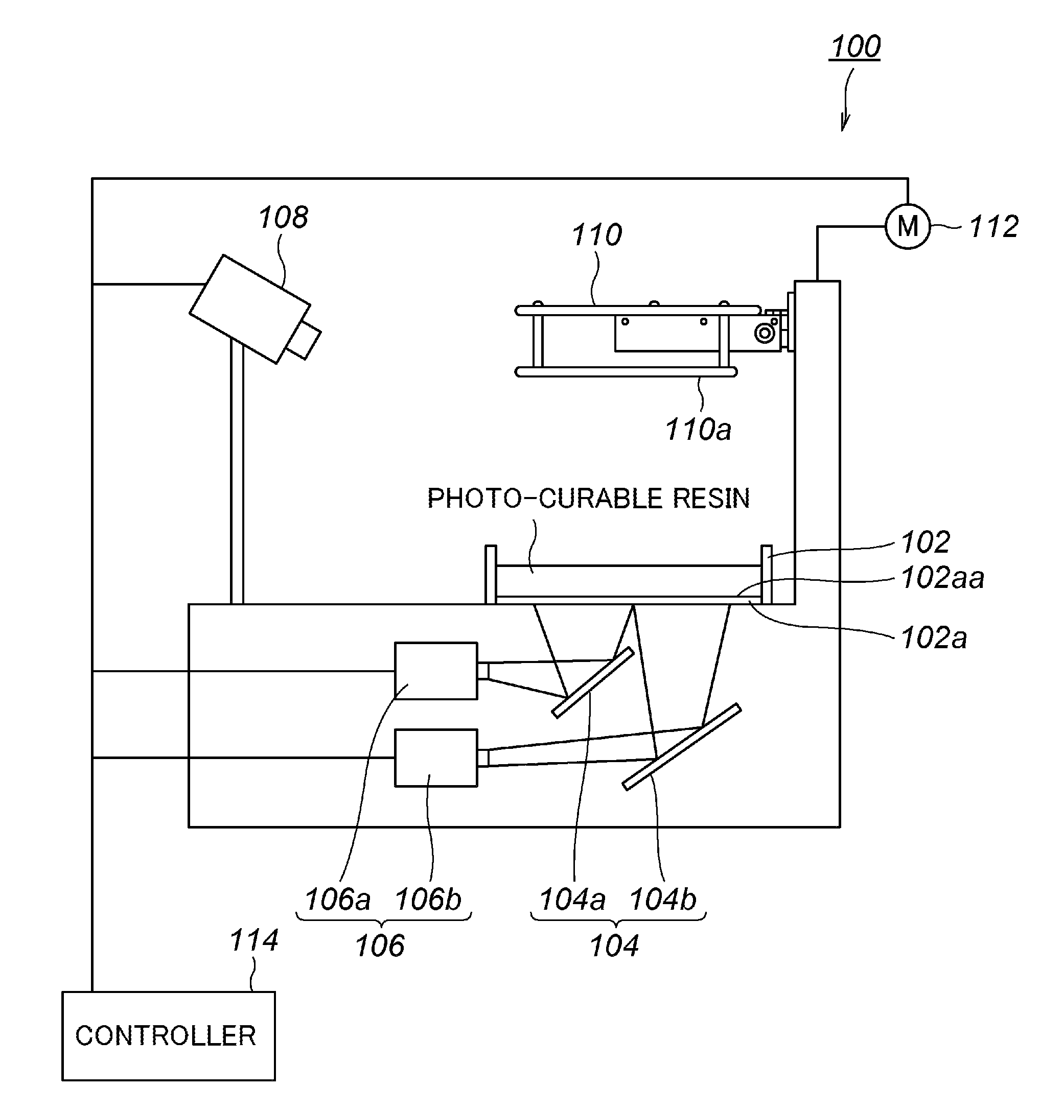
[0064]FIG. 1 is an explanatory diagram schematically illustrating a stereolithography apparatus 100 including an image projection system 10 according to a preferred embodiment of the present invention. FIG. 2 is an explanatory block diagram illustrating a hardware configuration of the image projection system 10 according to the present preferred embodiment.

[0065]As illustrated in FIG. 1, the stereolithography apparatus 100 preferably includes a container 102, a mirror 104, a projector 106, a camera 108, a shaped object holding section 110, a driving section 112, and a controller 114.

[0066]The container 102 stores a photo-curable resin in liquid form which is cured with irradiation of light such as visible light or ultraviolet light. A bottom wall 102a of the container 102 is provided by ...


PUM


Abstract

An image projection system projects a single image on an image projection region from a plurality of image projection sections and includes section that detects checker intersection coordinates in a corrected checkered sheet image, a section that calculates a first projective transformation matrix from the checker intersection coordinates, a section that generates first and second spatial code images, a section that acquires boundary lines in the first and second spatial code images, and acquires first intersection coordinates of the boundary lines, a section that calculates a second projective transformation matrix for projective transformation of the first intersection coordinates, transformed using the first projective transformation matrix, into second intersection coordinates distributed over an entire sub-region of the image projection region, and a section that transforms image data by using the second projective transformation matrix.

Description

[0001]This application claims priority to Patent Application No. 2013-144512 filed in Japan on Jul. 10, 2013, the entire contents of which are hereby incorporated by reference.BACKGROUND OF THE INVENTION[0002]1. Field of the Invention[0003]The present invention relates to image projection systems and image projection methods. More specifically, the present invention relates to an image projection system and an image projection method for projecting images on an image projection region from a plurality of image projection sections.[0004]2. Description of the Related Art[0005]A stereolithography apparatus that produces a three-dimensional shaped object by using a photo-curable resin in liquid form is conventionally known. A photo-curable resin has the property of being cured with irradiation of light such as visible light or ultraviolet light.[0006]As such a stereolithography apparatus, a “lifting type” stereolithography apparatus, for example, is used. In the lifting type stereolitho...

Claims


Application Information

Patent Timeline
IPC IPC(8): B29C67/00G05D25/02G05B15/02
CPCG05D25/02B29C67/0051G05B15/02B33Y50/02B29C64/124B29C64/393
InventorNAKAMURA, YASUTOSHI
OwnerROLAND DG CORP