
3D image photographing device
a 3d image and photographing device technology, applied in the field of 3d image photographing devices, can solve the problems of difficult to obtain stereoscopic effect from the 3d image, low application rate of the and high size and cost of the 3d conventional 3d image photographing device b>9/b>, so as to improve the utility of the 3d image photographing devi
- Summary
- Abstract
- Description
- Claims
- Application Information
AI Technical Summary
Benefits of technology
Problems solved by technology
Method used
Image

Examples
Embodiment Construction
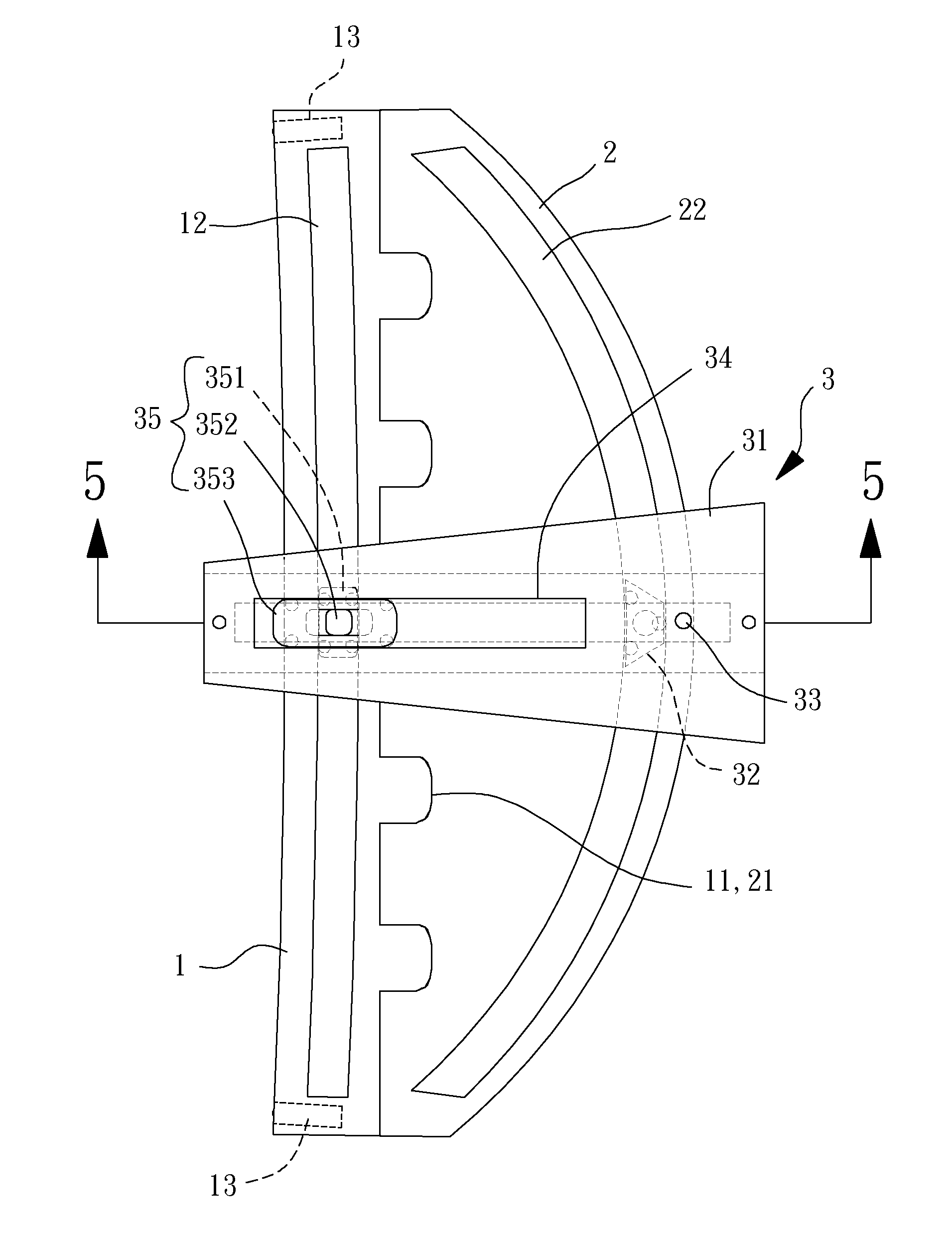
[0033]FIG. 3 is a perspective view of a 3D image photographing device of an embodiment according to the present invention. The 3D image photographing device includes a first track 1, a second track 2, a slide carriage 3 and a driving module 4. The first track 1 couples with the second track 2, the slide carriage 3 respectively couples with the first track 1 and the second track 2, and the driving module 4 is coupled to the slide carriage 3. The first track 1 has a first assembly portion 11 and the second track 2 has a second assembly portion 21. The first assembly portion 11 and the second assembly portion 21 are a pair of detachable engagement structures corresponding to each other, so that the first track 1 is able to detachably couple with the second track 2 through the first and second assembly portions 11, 21. Specifically, the first and second assembly portions 11, 21 may be a tenon and a mortise corresponding to each other for making an interlocking joint between the first an...
PUM
 Abstract
Description
Claims
Application Information