
Beverage mixing cartridge and method of using same
- Summary
- Abstract
- Description
- Claims
- Application Information
AI Technical Summary
Benefits of technology
Problems solved by technology
Method used
Image

Examples
Embodiment Construction
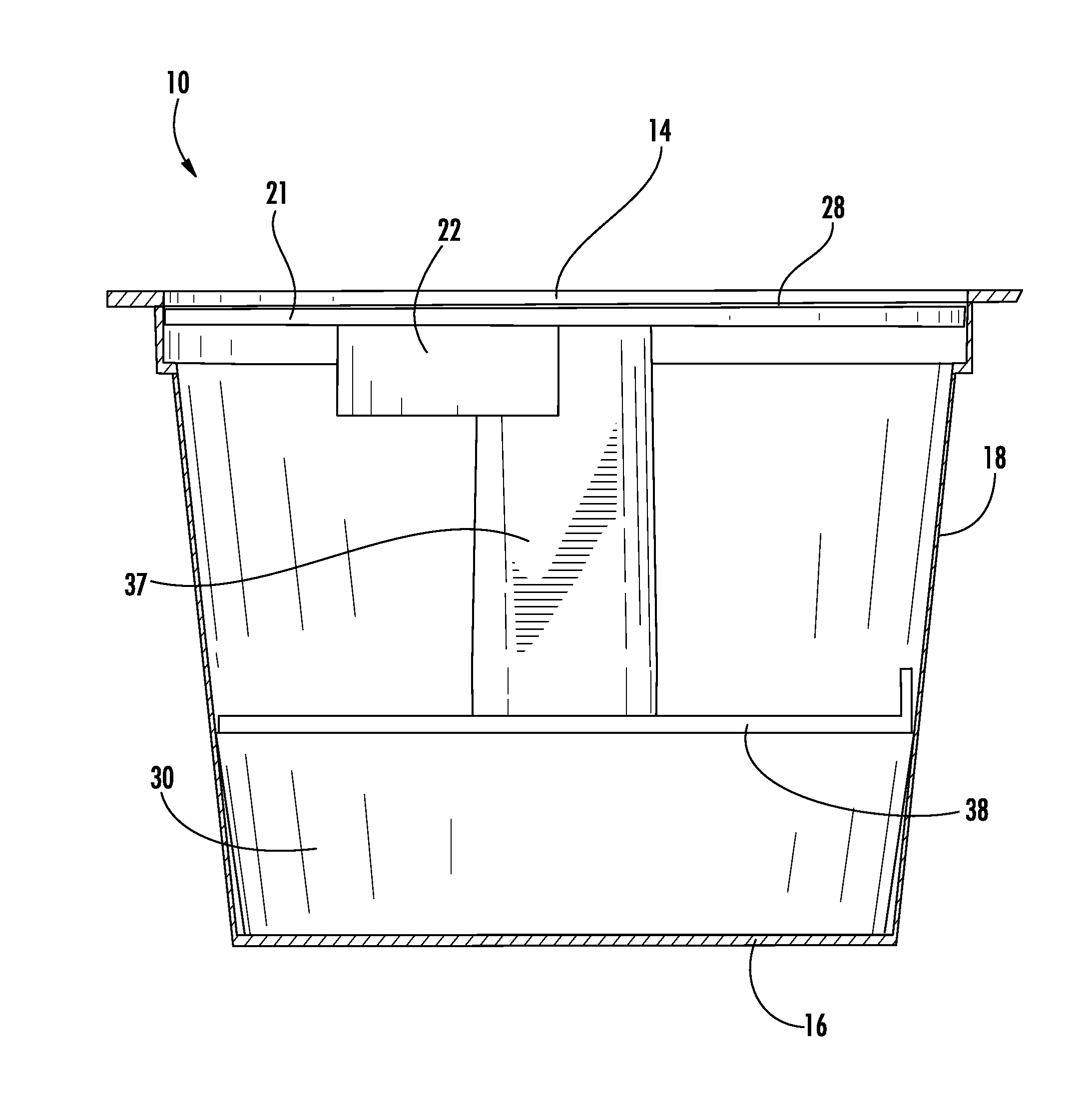
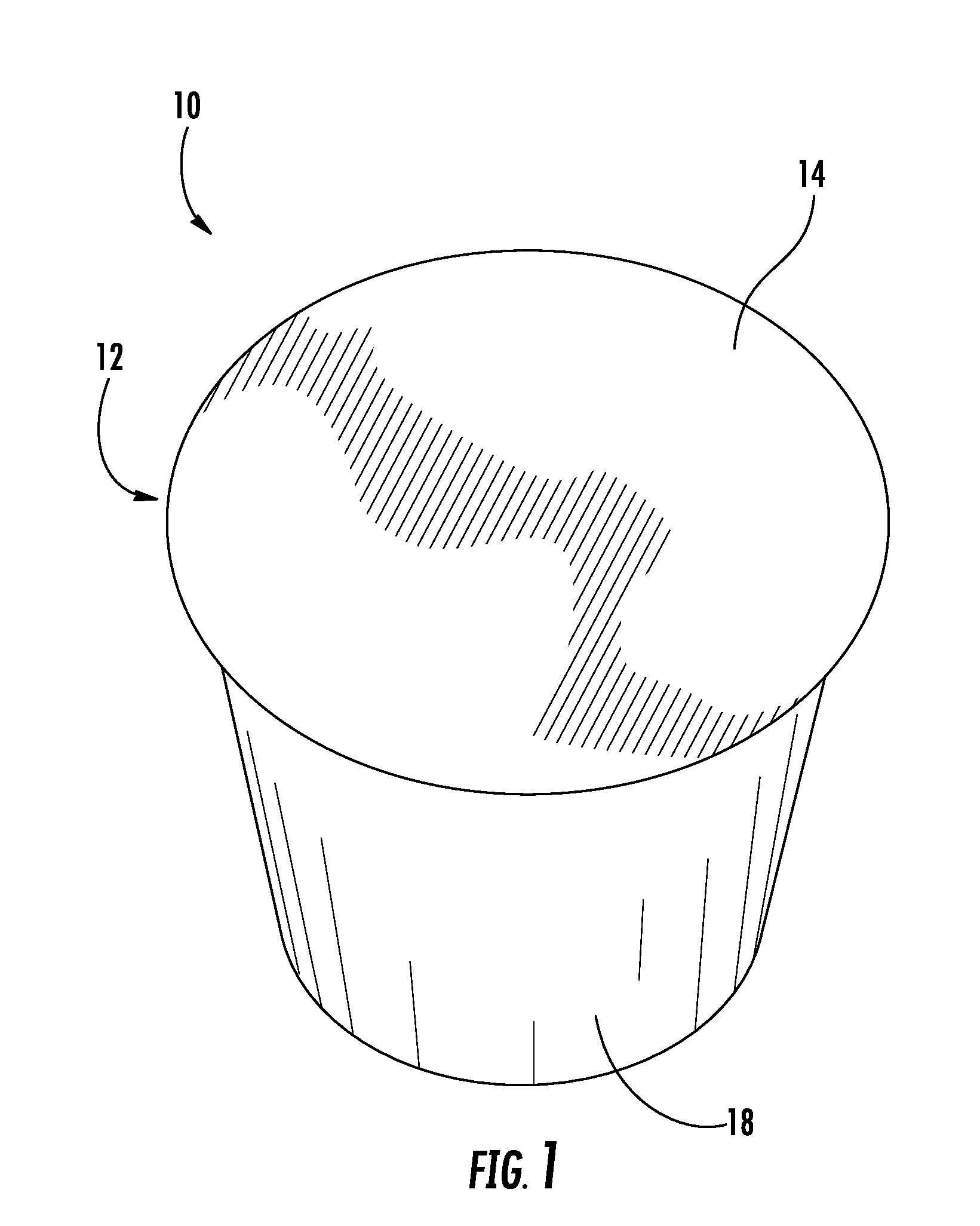
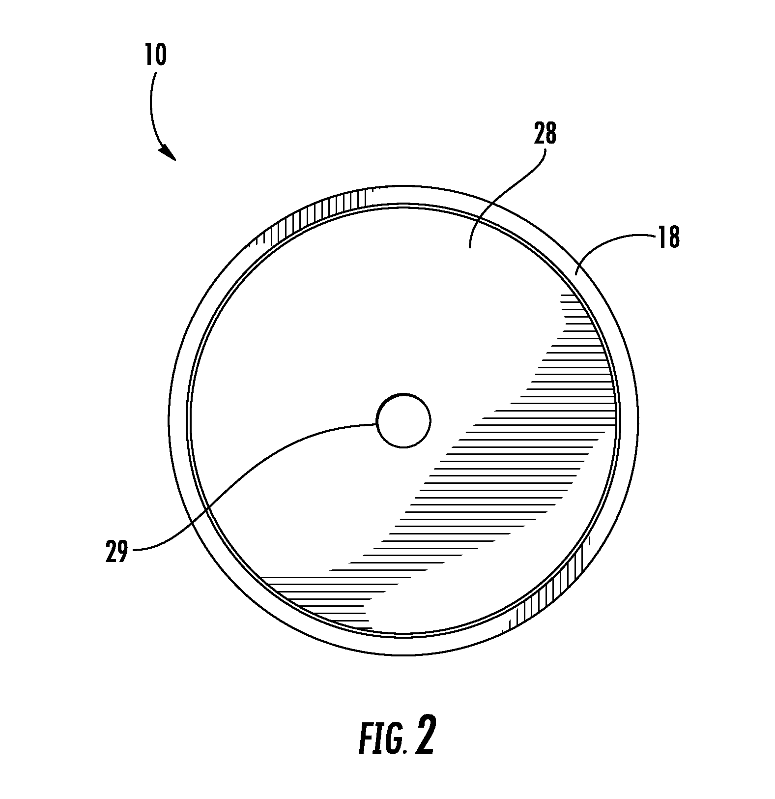
[0052]A single serve beverage cartridge according to a preferred embodiment of the invention is illustrated in FIGS. 1-11, and shown generally at reference numeral 10. The beverage mixing cartridge 10 comprises a conical housing 12 having a top wall 14, a base wall 16 and a side wall 18 connecting the top wall 12 to the base wall 14, as shown in FIGS. 1, 3 and 4.
[0053]The cartridge 10 includes two swirl-inducing sections that can receive liquid introduced into the cartridge 10, and cause the liquid to flow in a swirling or whirlpool-like motion. The first swirl-inducing section can be an upper channel section 20 positioned within the housing 12 proximate the top wall 12, as shown in FIGS. 3 and 4. The upper channel section 20 is comprised of a circular plate 21, and an arcuate channel 22 descending from the plate 21, as shown in FIGS. 3, 5 and 6. A substantially circular receptacle section 24 is formed at the center of the plate 21, and communicates with one end of the arcuate chann...
PUM
 Abstract
Description
Claims
Application Information