
Colloidal suspensions

Inactive Publication Date: 2010-07-01
SOMARK INNOVATIONS
View PDF8 Cites 2 Cited by
  • Summary
  • Abstract
  • Description
  • Claims
  • Application Information

AI Technical Summary

Benefits of technology

[0015]“Freeze-thaw resistant” means that after three freeze/thaw cycles, the composition retains one or more technical features of the invention.
[0016]

Problems solved by technology

These same properties which caused their success now limit their usefulness in commercial applications.
The simple design has low production costs, but is severely limited in the amount of data it can represent.
However, optical reading systems require a direct, unobstructed path for light to be emitted onto the barcode and then reflected back to the sensor.
This unobstructed (i.e., “line-of-sight”) property of optical read barcodes limits their usefulness.
RFID technology does, however, have its own problems.
Problems with this type of tag include cost of production due to the complexity of such a device as well as maintenance issues, physical size and weight constraints, and power consumption.
Passive tags overcome cost and complexity issues, but in turn have greatly restricted operability and flexibility.
Because a microchip is embedded in an RFID tag, along with radio frequency receivers, power supply, data memory, and transmitters, the device complexity and associated cost is much higher than that of optical barcodes.

Method used


Image

  • Colloidal suspensions
  • Colloidal suspensions
  • Colloidal suspensions

Examples


example 1

Preparation of Particulate Material

[0129]The following teaches methods of preparation of particulate material generally, and methods for preparation of sodium potassium niobate specifically. Potassium carbonate (20.4 g; 0.15 mol), sodium carbonate (15.6 g; 0.15 mol), niobium (V) oxide (77.3 g; 0.3 mol), purchased from Sigma Aldrich and Alfa Aesar, and ethanol (111 mL) were placed in a Nalgene bottle. Zirconia balls (645 g; 0.25 inch diameter) are added and the bottle agitated for 8 hours at room temperature, after which time the balls are removed and the mixture allowed to air dry.

[0130]The resulting solid was sieved through an 80 mesh sieve, and the isolated powder heated in an oven for 5 hours at 950° C. The resulting solid, ethanol (111 mL) and Zirconia balls (645 g; 0.25 inch diameter) were then placed into in a Nalgene bottle and agitated for 8 hours at room temperature. The balls were then removed, the mixture allowed to air dry, and the resulting solid was sieved through an 8...

example 2

Preparation of Sodium Potassium Niobate Sample for Analysis

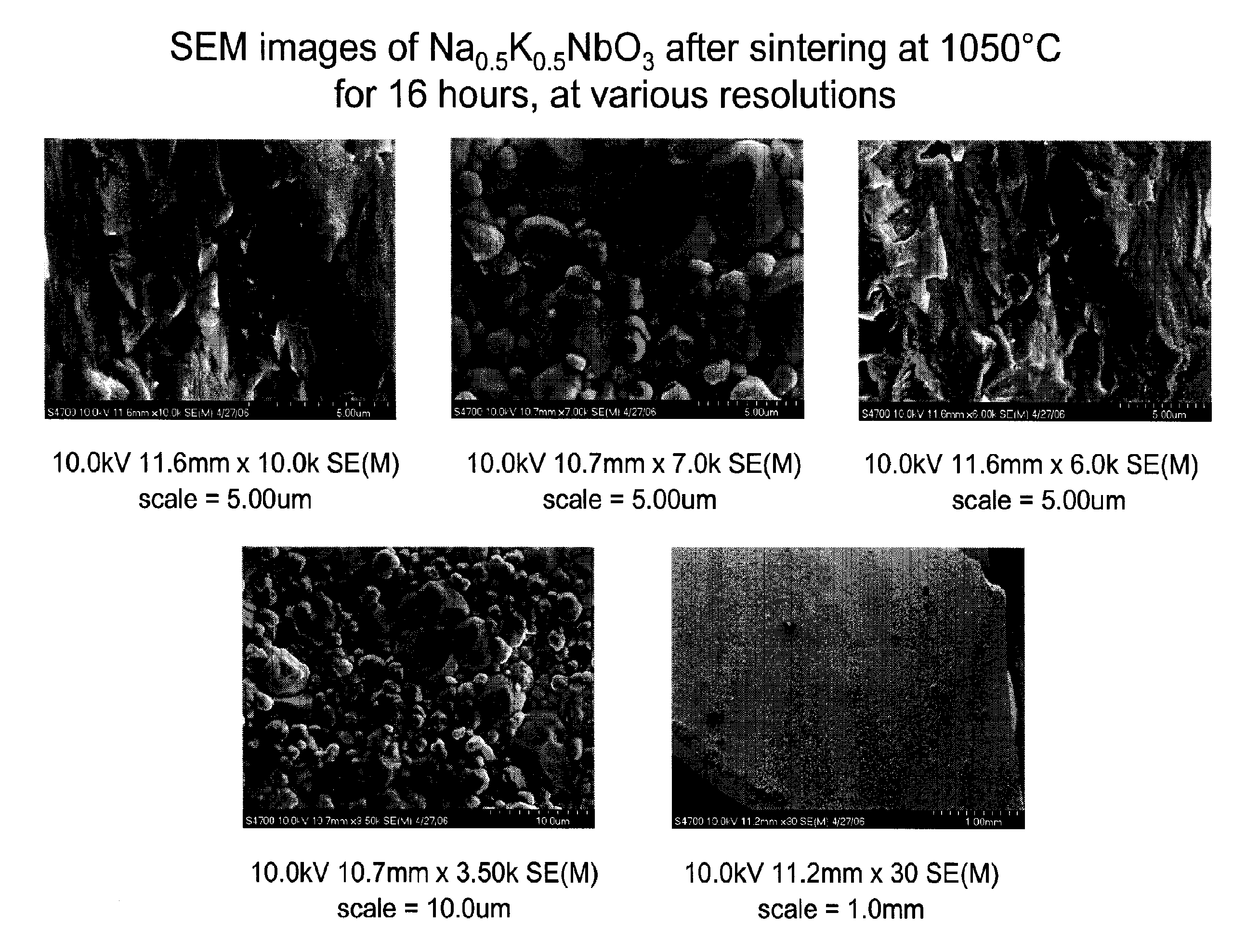
[0131]The sodium potassium niobate powder isolated in Example 11 was pressed at 1000 psi, cold iso-static pressed at 45,000 psi and sintered in air at 1050° C. for one hour, to produce a pellet suitable for analysis. The sample had the characteristics shown in Table 5:

TABLE 5Dry WeightSuspended Weight0.23gWet Weight0.42gLiquid Density0.817g / ccTheoretical Density4.51g / cc3Volume Open Porosity0.036Apparent Volume0.195Bulk Volume0.232% Open Porosity0.157Bulk Density1.677% Open Porosity0.157Bulk Density1.677Volume of closed porosity0.109% Closed Porosity0.47% Theoretical Density0.371

example 3

Particle Size Analysis of Sodium Potassium Niobate

[0132]The sodium potassium niobate sample prepared in example 2 was analyzed in a Beckman Coulter LS 230 Laser Diffraction Particle Size Analyzer, using standard operating procedures. Illustrative particle distributions are shown in FIG. 3.


PUM

PropertyMeasurementUnit
Temperatureaaaaaaaaaa
Lengthaaaaaaaaaa
Fractionaaaaaaaaaa

Abstract

Presented are compositions that when applied in a spatial manner so as to encode information, can remotely detected. Such compositions have liquid properties that make them adaptable to delivery by means such as a jet or needle injector. Instant compositions comprise a particulate material, a suspending agent, and a dispersing agent. Also taught are readable codes made by such compositions, and methods of applying such compositions. Other uses of such compositions are also taught

Description

CROSS-REFERENCE TO RELATED APPLICATIONS[0001]This application claims the benefit of U.S. Provisional Application Ser. No. 60 / 827,398 filed 28 Sep. 2006; hereby incorporated by reference herein in its entirety,TECHNICAL FIELD[0002]Described herein are compositions of a particulate material useful for application in an information-storing pattern.BACKGROUND[0003]Today uniform product code (UPC) labels are on practically every product produced in the world. Optical barcodes have become so widely accepted because of their low production costs, device complexity, and high durability. These same properties which caused their success now limit their usefulness in commercial applications. The simple design has low production costs, but is severely limited in the amount of data it can represent. The design also allows for simple and cheap detection through optical reading systems. However, optical reading systems require a direct, unobstructed path for light to be emitted onto the barcode an...

Claims


Application Information

Patent Timeline
IPC IPC(8): G06K7/10C09D11/00C09D11/10B32B3/10
CPCC08K5/005Y10T428/24802C09D11/30C08K7/00
Inventor MAYS, RAMOSHERB, CRAIG
Owner SOMARK INNOVATIONS
Learn More