Liquid storage unit, liquid discharge apparatus using the same, and method of removing bubbles from liquid storage unit

a liquid storage unit and liquid discharge technology, applied in the field of liquid storage units, can solve the problems of affecting the discharge, reducing the filling efficiency of liquid, and difficulty in increasing the thickness of the liquid storage chamber, so as to reduce the frequency of discharging bubbles

Active Publication Date: 2015-12-03
CANON KK
View PDF31 Cites 28 Cited by
  • Summary
  • Abstract
  • Description
  • Claims
  • Application Information

AI Technical Summary

Benefits of technology

[0006]It is an object of the present invention to provide a liquid storage unit capable of discharging bubbles in a liquid storage chamber to a liquid tank, and reducing the frequency of discharging the bubbles in the liquid storage chamber to the liquid tank.

Problems solved by technology

The air may cause decrease in filling efficiency of the liquid from the liquid tank to the liquid storage chamber, and the entry of air to the liquid discharge head may affect the discharge.
In the liquid discharge apparatus disclosed in Japanese Patent Application Laid-Open No. 2008-290419 and Japanese Patent Application Laid-Open No. 2002-370374, the entire liquid storage chamber needs to be expanded and contracted, thereby being difficult to increase the thickness of the liquid storage chamber.
On the other hand, the thin liquid storage chamber has high air permeability, and hence air is liable to enter the liquid storage chamber.
When a thick structure is employed for the purpose of reducing the air permeability of the liquid storage chamber, the liquid storage chamber cannot be expanded and contracted satisfactorily, thereby being difficult to discharge the bubbles in the liquid storage chamber to the liquid tank.

Method used


Image

  • Liquid storage unit, liquid discharge apparatus using the same, and method of removing bubbles from liquid storage unit
  • Liquid storage unit, liquid discharge apparatus using the same, and method of removing bubbles from liquid storage unit
  • Liquid storage unit, liquid discharge apparatus using the same, and method of removing bubbles from liquid storage unit

Examples


Embodiment Construction

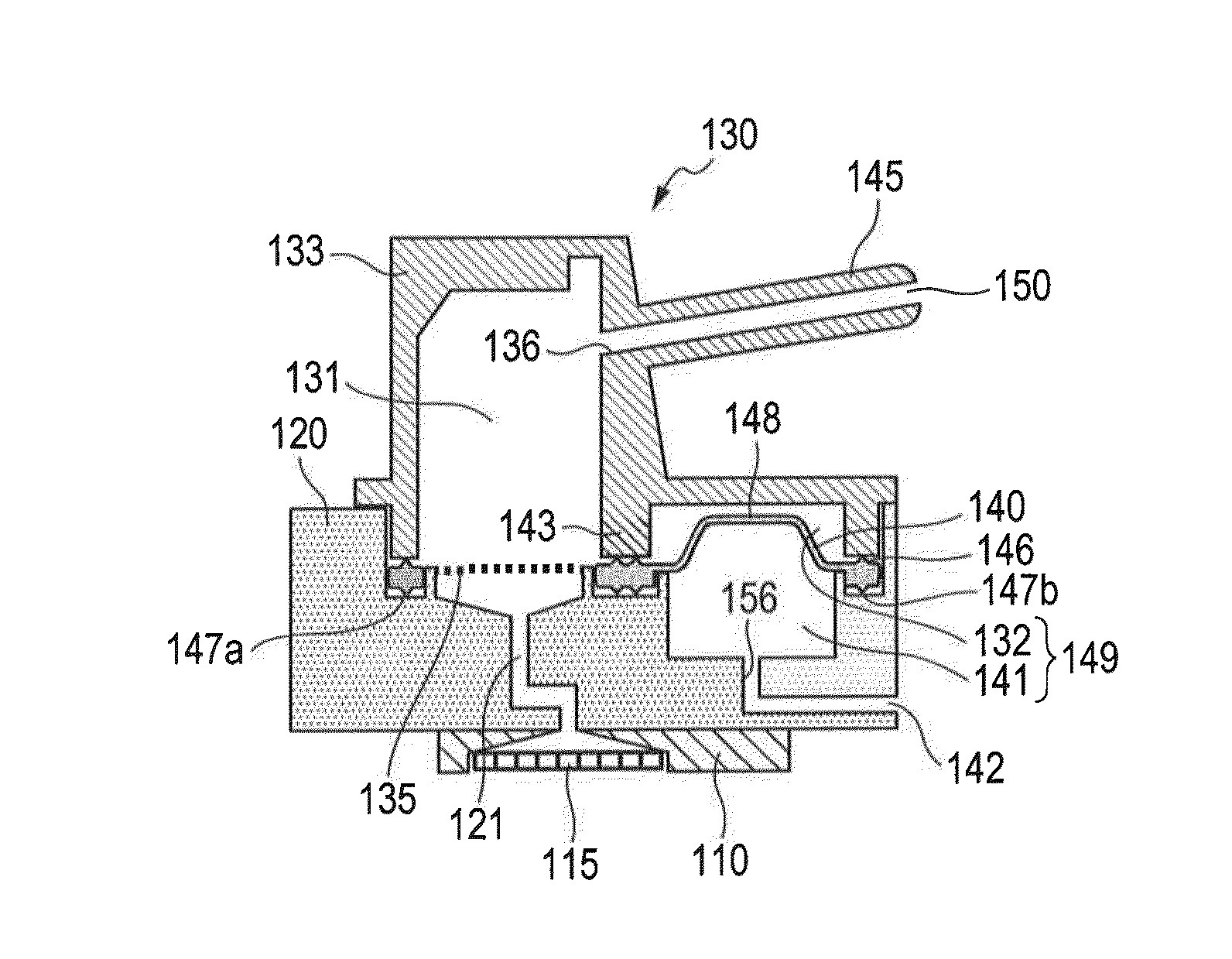
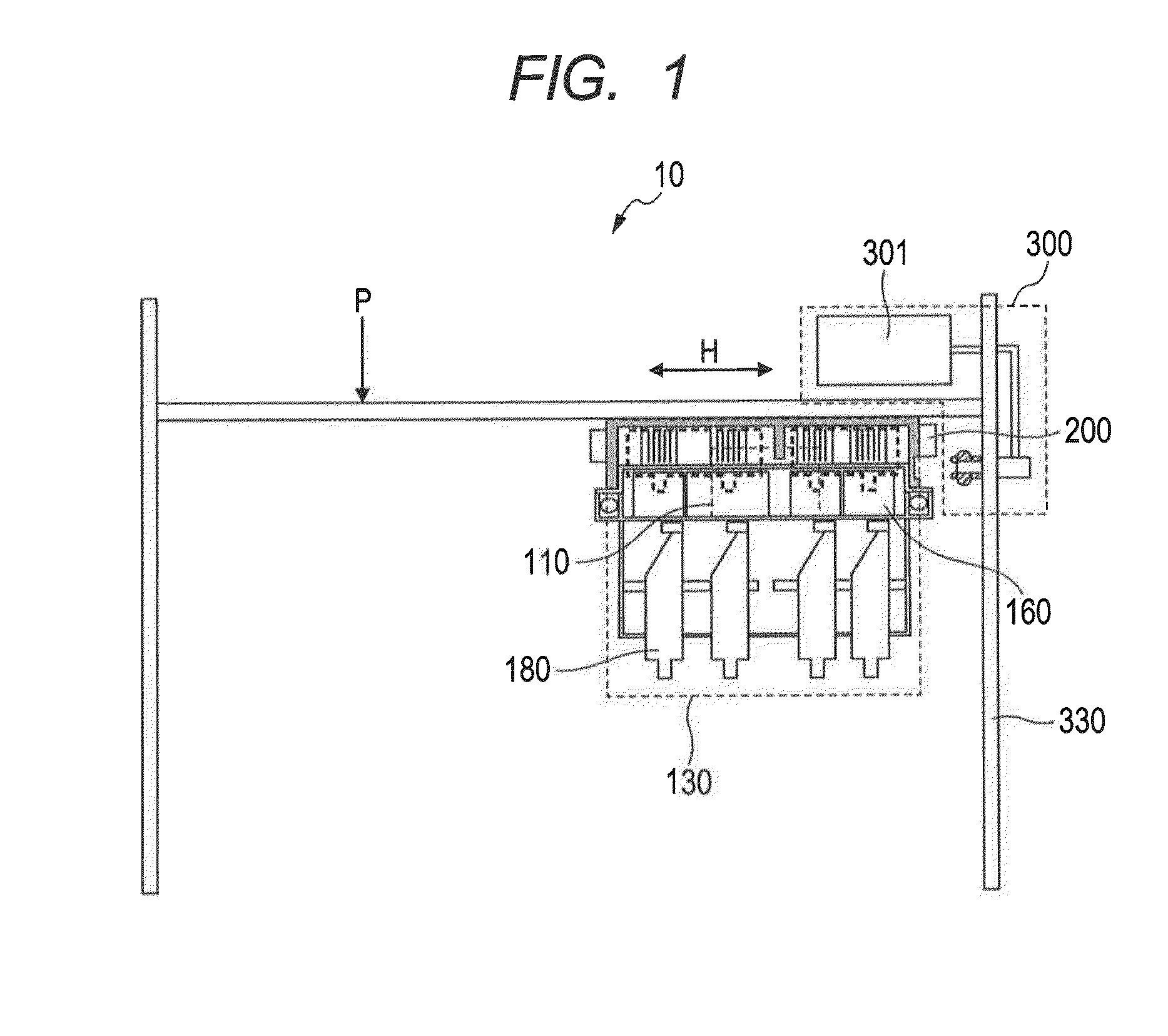
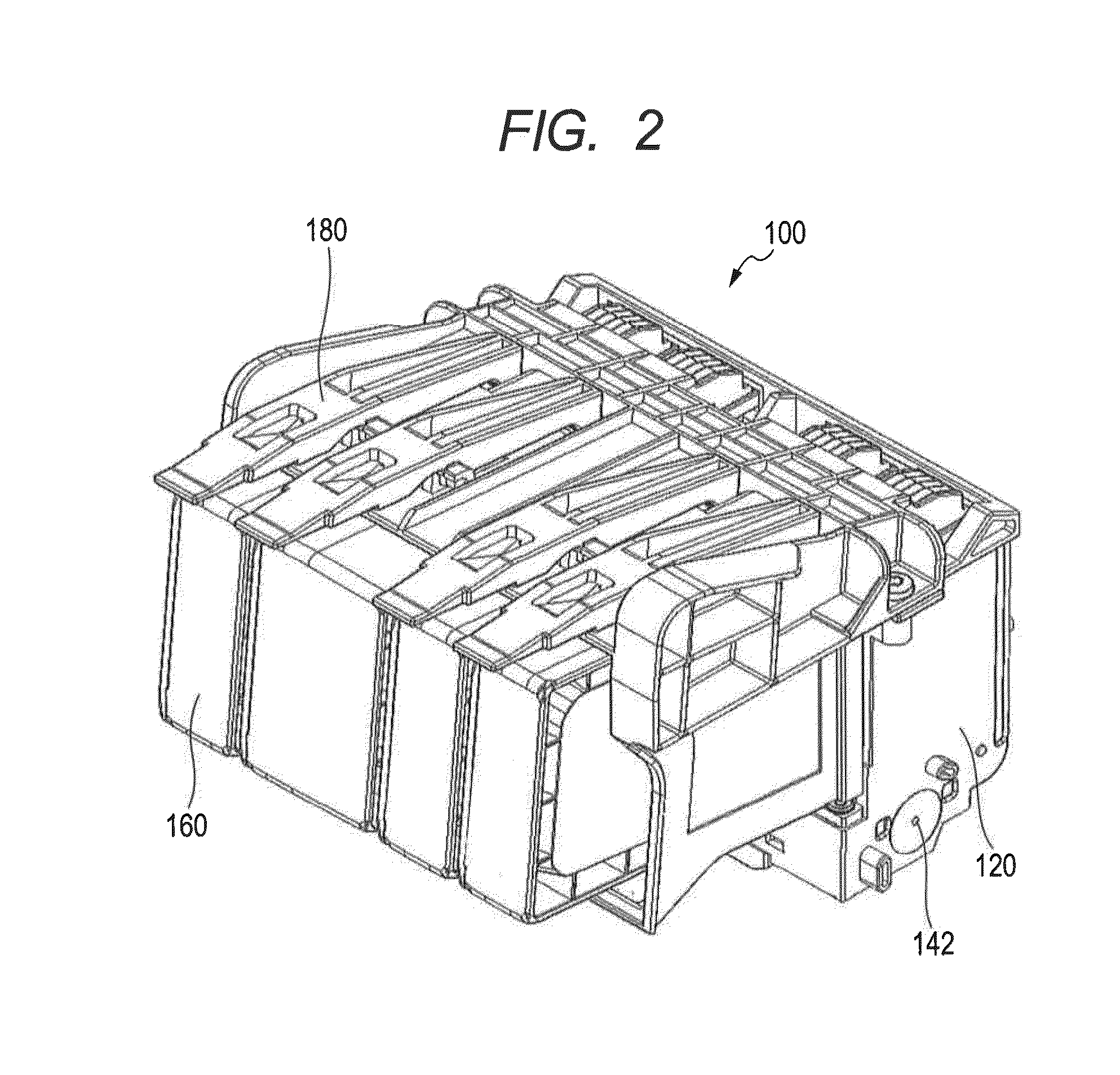
[0030]Now, embodiments of the present invention are described in detail with reference to the drawings. In the following embodiments, a liquid discharge head discharges liquid such as ink while moving relative to a recording medium, to thereby form an image. In the embodiments of the present invention, a liquid tank is removably mounted on the liquid discharge head, and liquid is directly supplied from the liquid tank to the liquid discharge head. The liquid tank together with the liquid discharge head is mounted on a carriage configured to conduct reciprocating motion (main). The present invention is also applicable to such a liquid discharge head and a liquid discharge apparatus that the liquid tank is not mounted on the liquid discharge head and the liquid tank and the liquid discharge head are connected to each other through a tube. In another embodiment of the present invention, a fixed liquid discharge head may discharge liquid onto a moving recording medium, to thereby form a...


PUM

PropertyMeasurementUnit
angleaaaaaaaaaa
angleaaaaaaaaaa
angleaaaaaaaaaa

Abstract

A liquid storage unit including a first liquid storage chamber having a constant volume and being capable of holding liquid supplied from a liquid tank; a second liquid storage chamber communicating with the first liquid storage chamber; a pressure control chamber configured to change a pressure of the pressure control chamber through actuation of a pressure control unit; and an elastic member being configured to tightly partition the second liquid storage chamber and the pressure control chamber from each other and being deformable so as to increase and decrease a volume of the second liquid storage chamber in accordance with the pressure of the pressure control chamber. The elastic member is capable of removing bubbles in the first liquid storage chamber by increasing and decreasing the volume of the second liquid storage chamber through the deformation.

Description

BACKGROUND OF THE INVENTION[0001]1. Field of the Invention[0002]The present invention relates to a liquid storage unit to be used in a liquid discharge apparatus configured to discharge liquid onto a recording medium, and more particularly, to a mechanism for removing bubbles from a liquid storage unit.[0003]2. Description of the Related Art[0004]A liquid discharge apparatus including a liquid tank and a liquid storage chamber configured to hold liquid supplied from the liquid tank and supply the liquid to a liquid discharge head is publicly known. Air may enter the liquid storage chamber due to various factors. The air may cause decrease in filling efficiency of the liquid from the liquid tank to the liquid storage chamber, and the entry of air to the liquid discharge head may affect the discharge. In Japanese Patent Application Laid-Open No. 2008-290419 and Japanese Patent Application Laid-Open No. 2002-370374, a liquid discharge apparatus including a liquid storage chamber having...

Claims


Application Information

Patent Timeline
Patent Type & Authority Applications(United States)
IPC IPC(8): B41J2/19B01D19/00
CPCB01D19/0073B41J2/19B41J2/17513B41J2/17509B41J2/17556B65D81/00
Inventor TAKADA, HITOSHIKOTAKI, YASUOOHASHI, TETSUYAINOUE, RYOJIKITAGAWA, TAKATOSHIMURAKAMI, HIRONORIMIYASHITA, TAKEHOHAYASHI, HIROKIFUKUCHI, HIRONORIIKEBE, NORIHIROFUKUSHIMA, TAKASHI
Owner CANON KK
Why Eureka
Try Eureka