Modularly Redundant DC-DC Power Supply Arrangement Having Outputs That Can Be Connected In Parallel

Active Publication Date: 2016-01-07
SIEMENS AG
View PDF6 Cites 1 Cited by
  • Summary
  • Abstract
  • Description
  • Claims
  • Application Information

AI Technical Summary

Benefits of technology

[0031]In one embodiment, the method further comprises predetermining a maximum permitted output voltage for a voltage regulating unit of the output switching controller which is activated as a decoupling diode in each case. The maximum permitted output voltage corresponds in this case to any voltage which is permissible for a load that is to be supplied. This provides an effective overvoltage p

Problems solved by technology

This results in uneven wear of the two supply units, whereby it can be assumed that one of the two units will have a shorter service life.
Diodes result in excessive losses when higher powers are supplied.
Here, likewise, the wear of th

Method used


Image

  • Modularly Redundant DC-DC Power Supply Arrangement Having Outputs That Can Be Connected In Parallel
  • Modularly Redundant DC-DC Power Supply Arrangement Having Outputs That Can Be Connected In Parallel
  • Modularly Redundant DC-DC Power Supply Arrangement Having Outputs That Can Be Connected In Parallel

Examples


Embodiment Construction

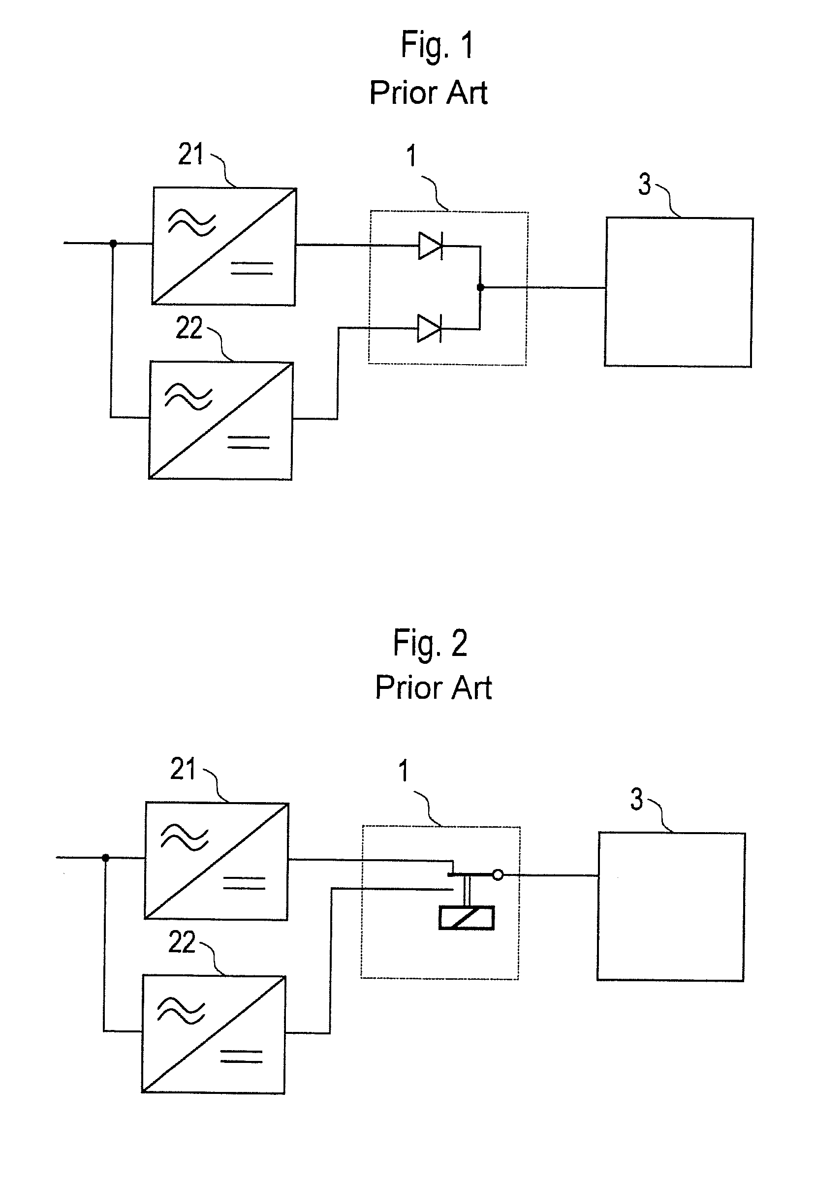
[0042]FIGS. 1 and 2 show redundant power supply arrangements as per the prior art. In this case, a redundancy circuit 1 coupled to a load 3 is connected to two separate supply units 21, 22. Each of these supply units 21, 22 represents a separate power supply device.

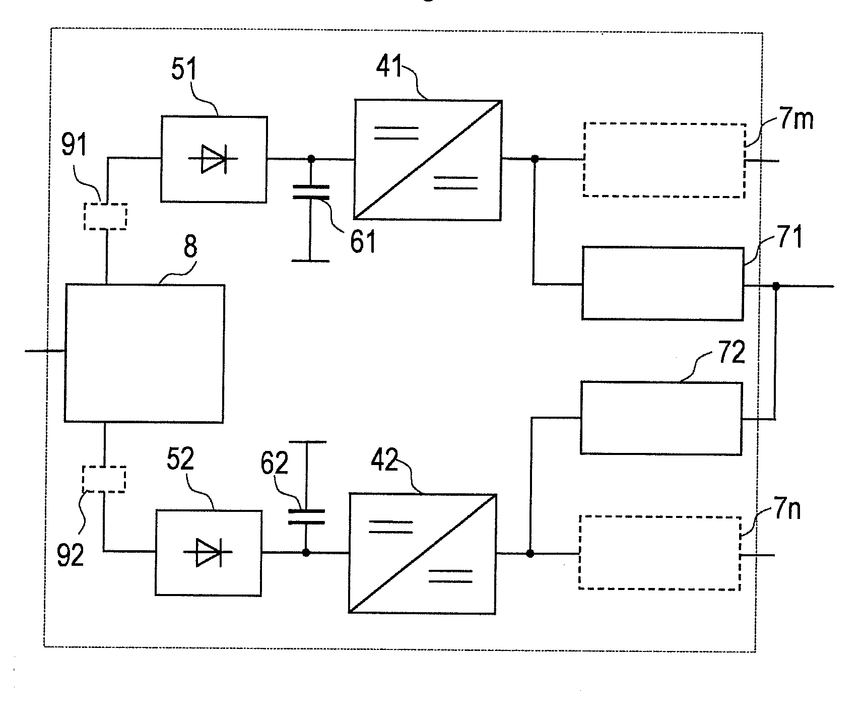
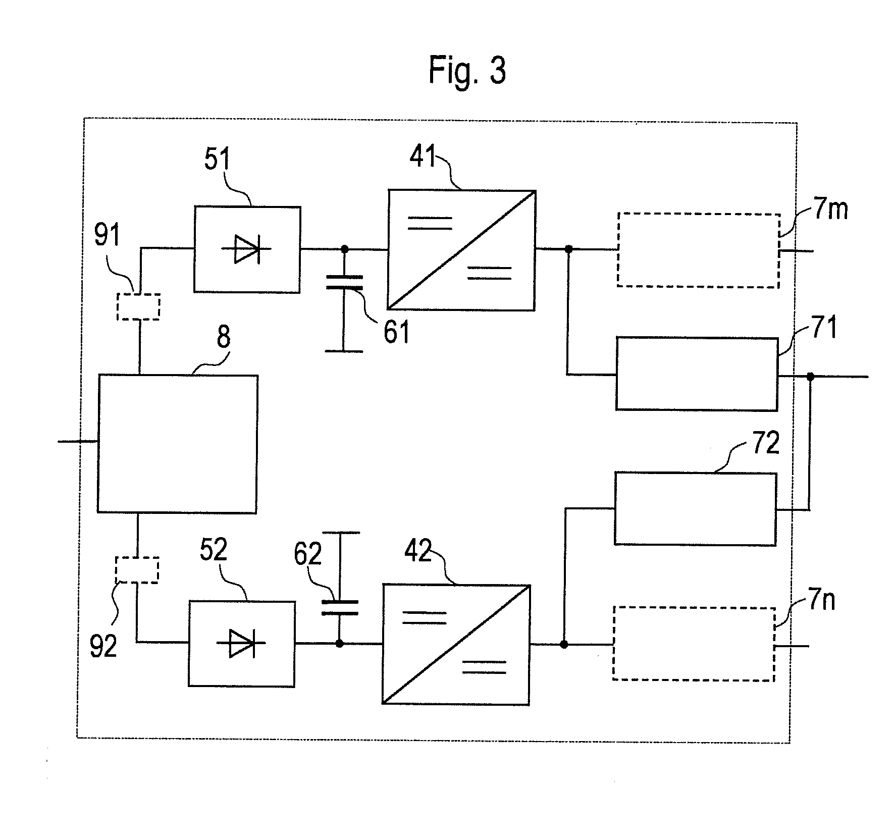
[0043]By contrast, according to the present invention, a power supply arrangement for redundantly supplying power to a load is adapted as a single device in a housing, wherein components not relevant to safety are included only once.

[0044]As shown in FIG. 3, a power supply arrangement in accordance with one embodiment comprises only one passive filter 8, via which two paths are connected to a supply network. Each path comprises a rectifier unit 51 or 52, a DC link with capacitor 61 or 62, a DC-DC converter 41 or 42 and at least one output switching controller 71 or 72. A plurality of output switching controllers 71, 7m or 72, 7n can also be connected to each DC-DC converter 41 or 42, respectively.

[0045]A protection unit 9...


PUM


Abstract

A power supply device for redundantly supplying power to a load comprises a first supply unit, a second supply unit, a first DC-DC converter, a second DC-DC converter, a first output switching controller, and a second output switching controller. The first and second supply units are interconnected. The first output switching controller is connected on the load side of the first DC-DC converter, and the second output switching controller is connected on the load side of the second DC-DC converter. The outputs of the output switching controllers are interconnected.

Description

CROSS-REFERENCE TO RELATED APPLICATIONS[0001]This is U.S. national stage of PCT Application No. PCT / EP2013 / 050621, filed on Jan. 15, 2013, which claims priority to European Patent Application No. EP 12153970.4, filed on Feb. 6, 2012, each of which is hereby incorporated herein in its entirety by reference.FIELD OF INVENTION[0002]The invention relates to a power supply arrangement for redundantly supplying power to a load, wherein the power supply arrangement comprises a first supply unit and a second supply unit that are interconnected.DESCRIPTION OF THE RELATED ART[0003]Electrical installations are often governed by particular safety requirements or the need for high availability. Critical parts of such installations are implemented to offer redundancy in order to prevent failure of the installation if a fault occurs. This also relates to power supply arrangements.[0004]According to the prior art, a redundant power supply arrangement includes two separate supply units whose outputs...

Claims


Application Information

Patent Timeline
IPC IPC(8): H02M3/158H02J1/10
CPCH02J1/10H02M3/158H02J1/102H02J9/06H02M3/1584H02M3/33523H02M1/007Y02B70/10Y02P80/10
Inventor AUGESKY, CHRISTIANSCHWEIGERT, HARALD
Owner SIEMENS AG
Why Eureka
Try Eureka