Power supply stage of an electric appliance, in particular a battery charger for charging batteries of electric vehicles

a technology for electric vehicles and power supply stages, which is applied in the direction of safety/protection circuits, emergency protective arrangements for limiting excess voltage/current, transportation and packaging, etc., can solve the problems of loss of neutral connection, high value, and danger to the integrity of user devices, and achieve high reaction speed and high dissipation of component switches

Active Publication Date: 2018-12-18
META SYST
View PDF26 Cites 0 Cited by
  • Summary
  • Abstract
  • Description
  • Claims
  • Application Information

AI Technical Summary

Benefits of technology

[0023]The main aim of the present invention is to provide a power supply stage of an electric appliance, in particular a battery charger for charging batteries of electric vehicles, which ensures an effective overvoltage protection in an efficient manner and with affordable costs.
[0024]Another object of the present invention is to provide a power supply stage of an electric appliance, in particular a battery charger for charging batteries of electric vehicles, which allows to overcome the mentioned drawbacks of the prior art within the framework of a simple, rational, easy and effective to use solution.

Problems solved by technology

It is further known that one of the most hazardous events in systems powered by three-phase voltage with neutral, in the event of the three voltages being used as single-phase voltages, is the loss of the neutral connection.
It therefore follows that the starred voltages can also take on very high values with consequent danger for the integrity of the user devices.
In particular, in the single-phase electronic systems connected to a three-phase power supply, the loss of the neutral can result in the components at supply unit input undergoing voltages in excess of plate values.
Furthermore, this solution necessarily requires manual intervention to reset the line and the overcurrent protection and this is not always possible nor “acceptable” to the end user, especially if the protection consists of a fuse and not a resettable thermal magnetic switch.

Method used


Image

  • Power supply stage of an electric appliance, in particular a battery charger for charging batteries of electric vehicles
  • Power supply stage of an electric appliance, in particular a battery charger for charging batteries of electric vehicles
  • Power supply stage of an electric appliance, in particular a battery charger for charging batteries of electric vehicles

Examples


Embodiment Construction

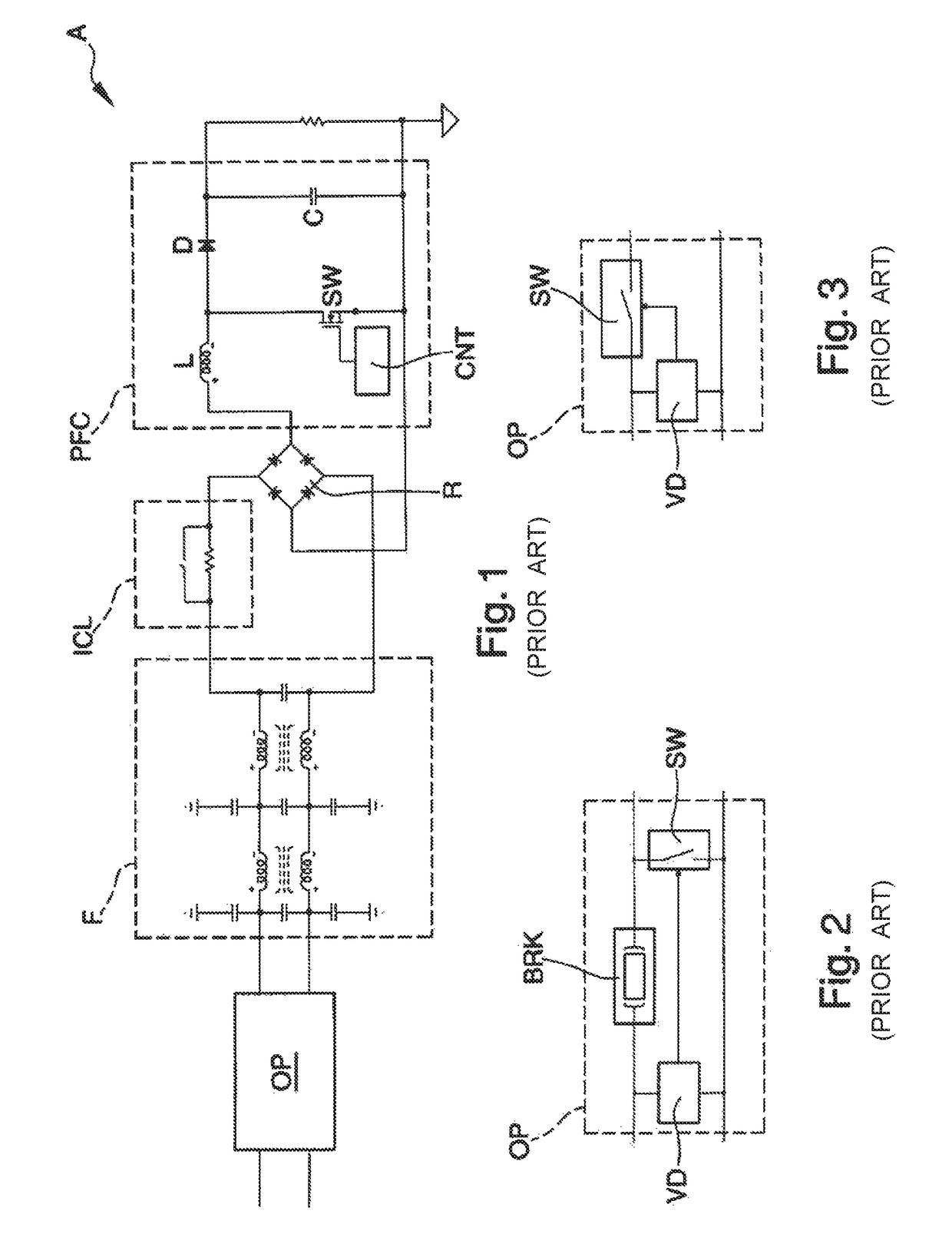
[0031]With particular reference to such figures, globally indicated with A is a power supply stage of an electric appliance, usable in particular as a power supply stage of a battery charger for charging batteries of electric vehicles.

[0032]The use of the power supply stage A for electronic devices and equipment of different kind cannot however be ruled out.

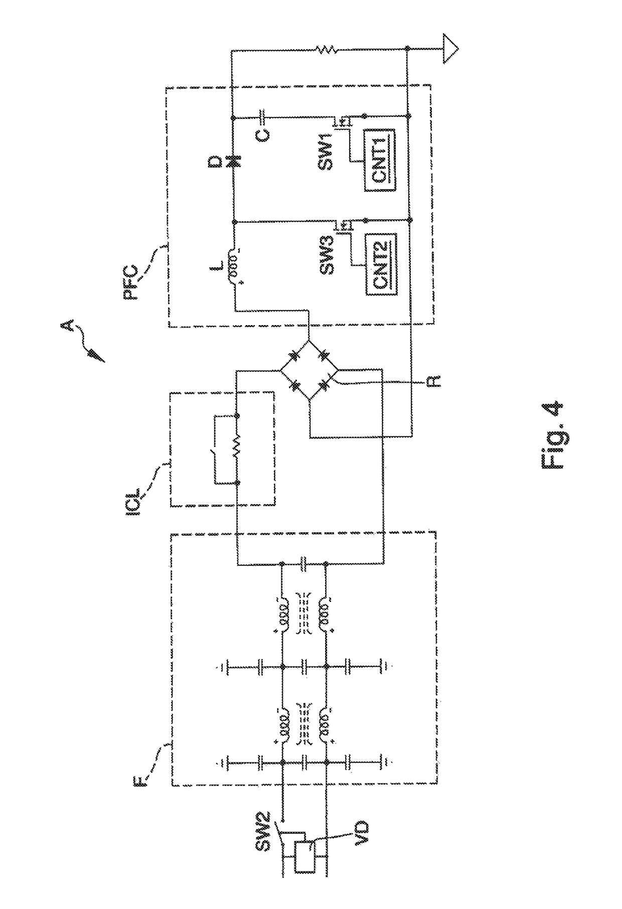
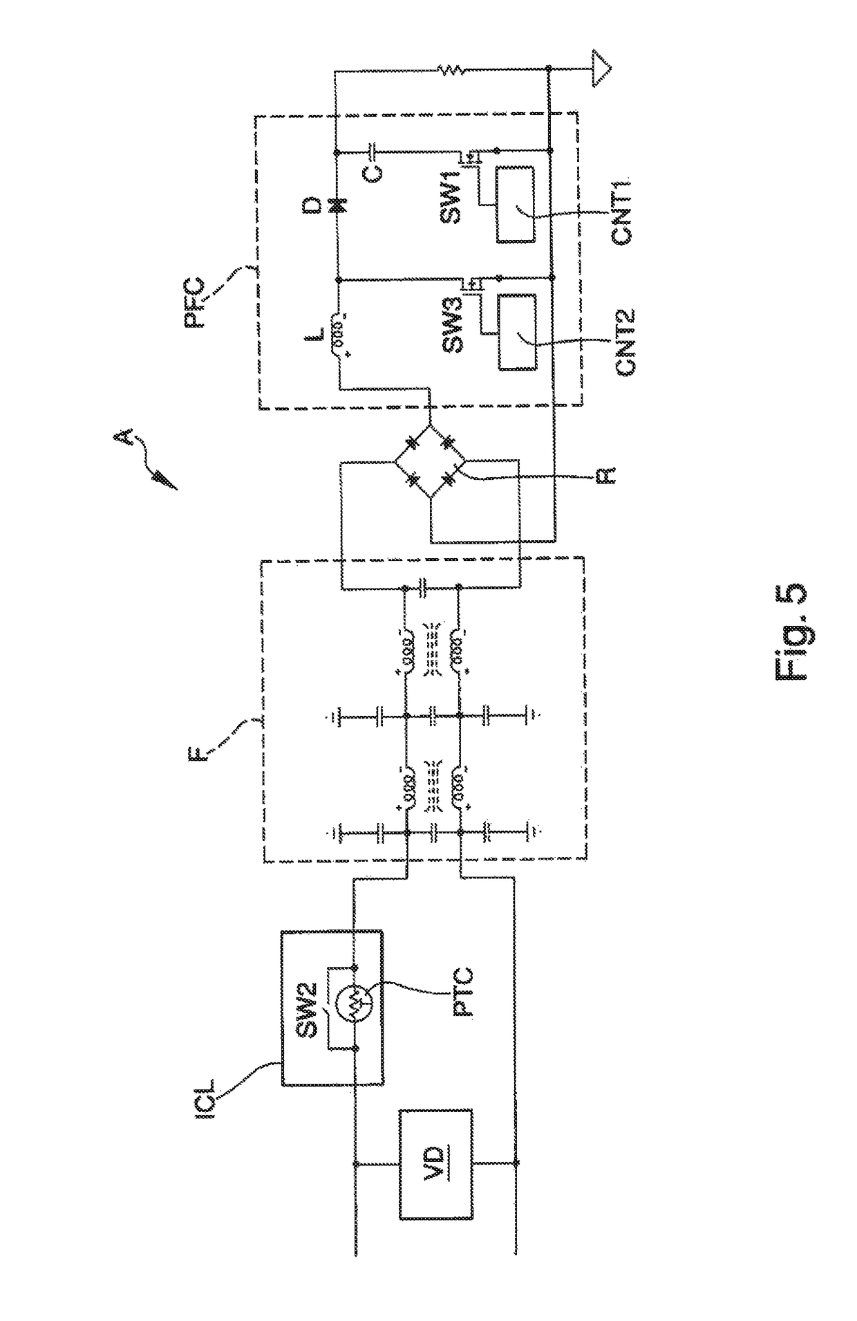
[0033]In particular, with reference to a first embodiment shown in FIG. 4, the power supply stage A comprises an input filter F connectable to an external power supply line, an ignition current limiter ICL connected downstream of the input filter F, a rectifier bridge R connected to the input filter F and to the ignition current limiter ICL, and a power factor correction circuit PFC connected downstream of the rectifier bridge R.

[0034]More specifically, the power factor correction circuit PFC comprises an input inductor L, at least a rectifying diode D and at least a smoothing capacitor C connected downstream of the rectifying di...


PUM


Abstract

The power supply stage (A) of an electric appliance, in particular battery chargers for charging batteries of electric vehicles or the like, comprises a power factor correction circuit (PFC), and overvoltage protection means equipped with:a switch (SW1) connected in series with a smoothing capacitor (C) of the power factor correction circuit (PFC);a control circuit (VD1) of the input voltage of the power supply stage (A) operatively connected to the switch (SW1).

Description

RELATED APPLICATIONS[0001]This application is a National Phase of PCT Patent Application No. PCT / IT2015 / 000055 having International filing date of Mar. 3, 2015, which claims the benefit of priority of Italian Patent Application No. MO2014A000070 filed on Mar. 17, 2014. The contents of the above applications are all incorporated by reference as if fully set forth herein in their entirety.FIELD AND BACKGROUND OF THE INVENTION[0002]The present invention relates to a power supply stage of an electric appliance, usable in particular in battery chargers for charging batteries of electric vehicles.[0003]The use is known and common of battery chargers generally integrated inside an electric vehicle, connectable at input to an alternate current power line and connected at output to an electric battery of the electric vehicle.[0004]By way of example, a possible power supply stage A of a battery charger of known type is shown in FIG. 1 and comprises an input filter F, which can be connected to...

Claims


Application Information

Patent Timeline
Patent Type & Authority Patents(United States)
IPC IPC(8): H02J7/00H02H9/04H02H9/00H02J7/02B60L11/18H02M1/42H02J5/00B60L11/00H02M1/32H02H3/20H02H7/18
CPCH02J7/0029B60L11/1811H02H3/20H02H9/001H02H9/041H02J5/00H02J7/02H02M1/32H02M1/4225H02J7/0052Y02T90/127H02H7/18H02J2007/0059Y02B70/126H02J7/027B60L53/20H02H7/12H02M1/42H02J7/00308Y02B70/10H02J2207/20Y02T90/12Y02T90/14Y02T10/70Y02T10/7072H02J7/00
Inventor LASAGNI, CESARE
Owner META SYST
Why Eureka
Try Eureka