Atmospheric Water Generation Systems

a technology of atmospheric water and water generation system, which is applied in the direction of heating types, separation processes, domestic cooling apparatus, etc., can solve the problems of increasing the difficulty of meeting the water requirements of growing populations, increasing the difficulty of supplying water, and expensive bottled water, etc., and achieves the effect of convenient transportation and deploymen

Active Publication Date: 2016-02-04
SEAS SOC DE LEAU AERIENNE SUISSE
View PDF5 Cites 13 Cited by
  • Summary
  • Abstract
  • Description
  • Claims
  • Application Information

AI Technical Summary

Benefits of technology

[0008]Starting from this background an object of an embodiment of the present invention is to provide an improved atmospheric water generating apparatus which is readily transported and deployed using standard commercial transport systems.

Problems solved by technology

It is in short supply in many parts of the world, and in the future it will become more even challenging to supply the water requirements of growing populations.
Climate change effects have begun to alter expected weather and water patterns, and these changes, combined with an ever-increasing human population and increased water requirements for domestic, agriculture and industrial sectors has led and will lead to shortages.
The problem is particularly acute in places such as tropical islands, and floating installations such as oil rigs, and at remote or tropical locations that lack a water supply infrastructure.
For example, on many islands, consumers must purchase expensive bottled water, or refill water jugs with water of questionable purity at local water stations.
There are no wells, most houses are not on city water and even if they are, the city water is not potable.
Such water is often of questionable purity and flavor.
The problem is also found in places where the existing water infrastructure has not been maintained.
Water pipes may leak, cisterns may be cracked, such that the quantity of available water is less than amounts available a century ago.
In addition, such systems also are at risk for contamination of the water supply from such leaks and from other causes.
However, such systems, whether large or small, have been dependent on an electrical system infrastructure to operate the systems.
Small water cooler size systems, while portable, have insufficient capacity to supply the needs of a substantial population.
Larger installations are all custom built and are not designed to be readily deployed using standard commercial transport systems.

Method used


Image

  • Atmospheric Water Generation Systems
  • Atmospheric Water Generation Systems
  • Atmospheric Water Generation Systems

Examples


Embodiment Construction

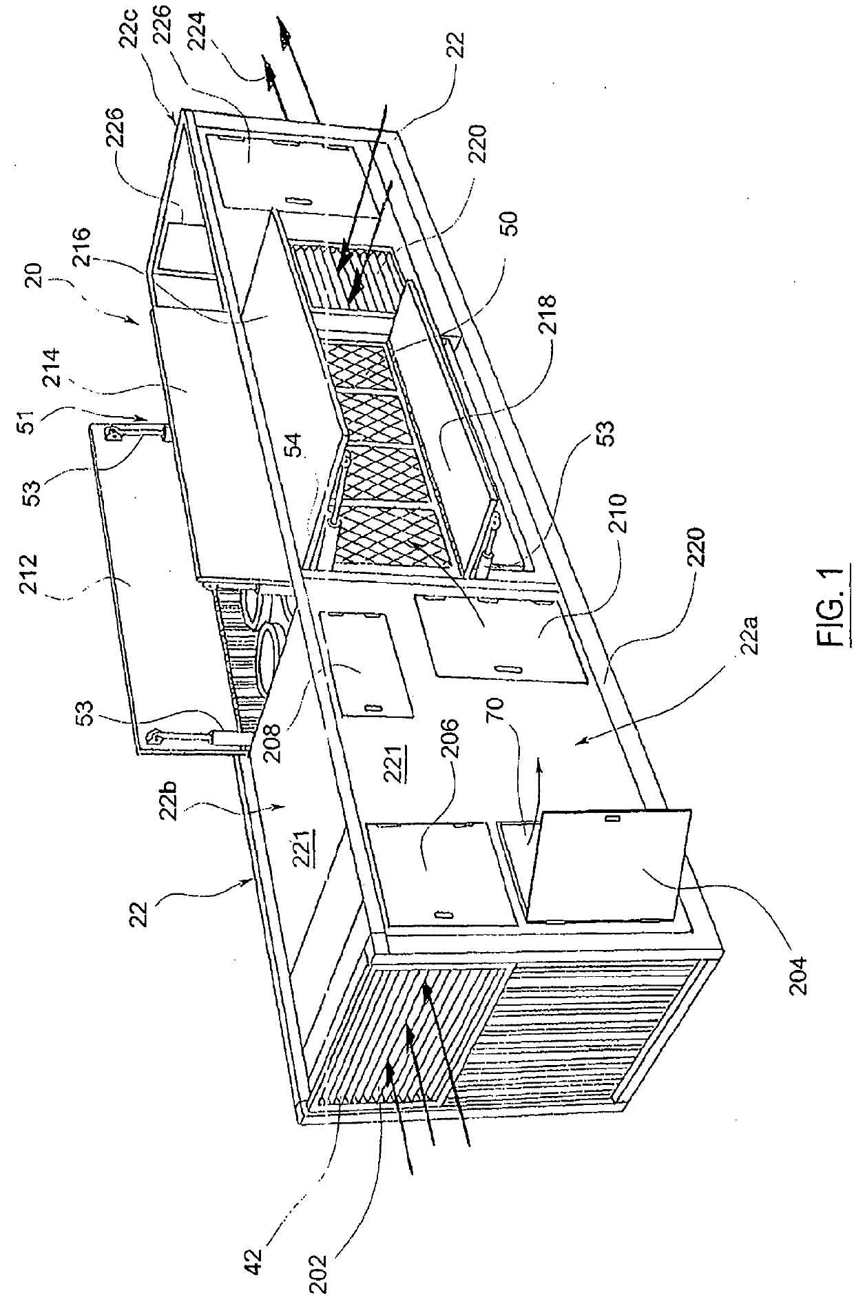
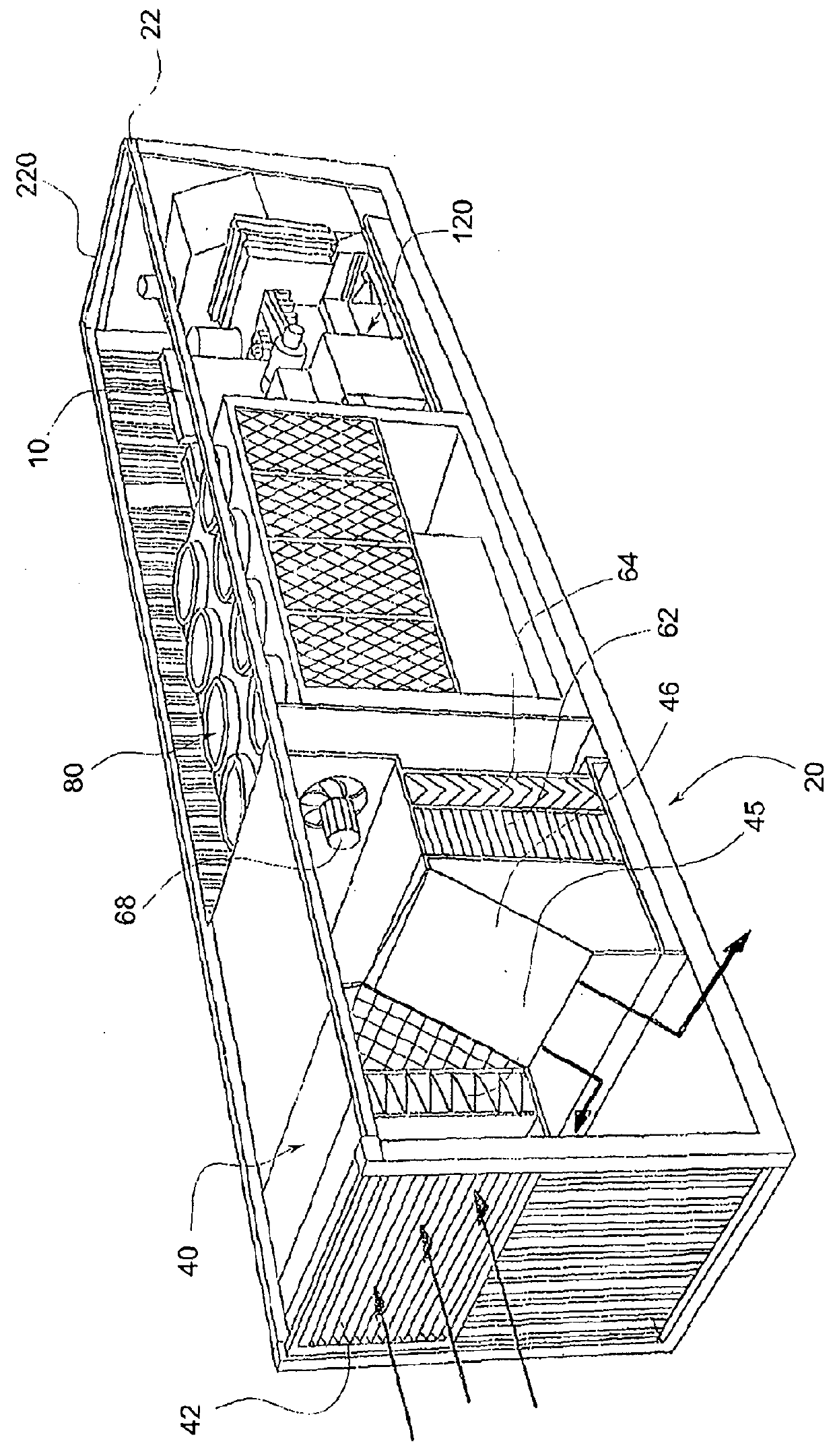
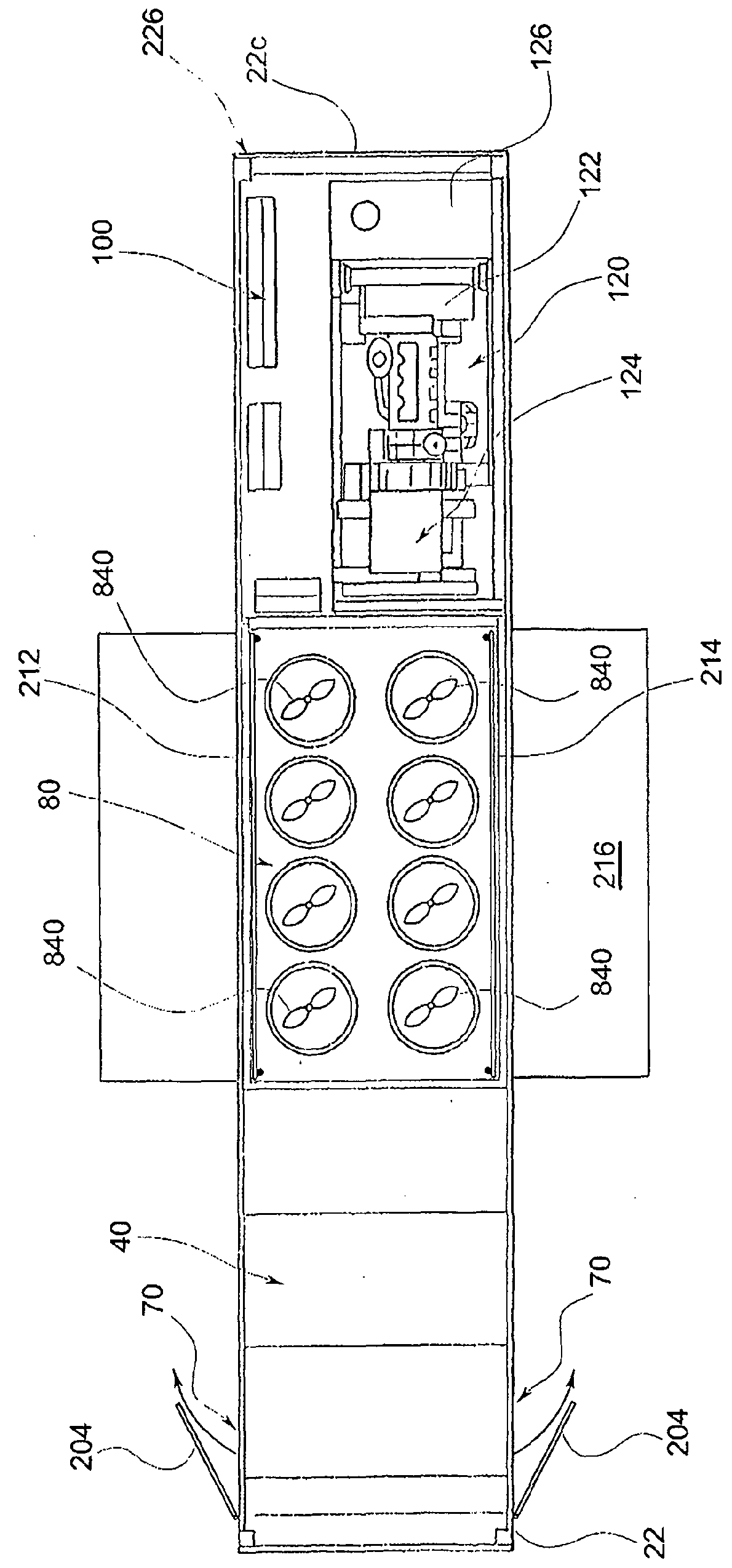
[0027]Referring now to FIGS. 1-5, where like numerals indicate the same elements in the Figures, an atmospheric water generation system 20 is shown.

[0028]Atmospheric water generation system 20 comprises at least an air treatment unit 40 associated with a chiller unit 80, and a water treatment unit 100.

[0029]According to the illustrated embodiment of the invention the atmospheric water generation system 20 comprises an electric generator system 120 (FIG. 3).

[0030]Atmospheric water generation system 20 is a high performance integrated water production machine which is assembled into a casing having a parallelepiped shaped and comprising a tubular frame 220 (FIG. 2) externally closed by metallic undulated panels 221. The casing has a standard shipping container size, specifically a container 22 which is the size of a ISO standard 40′ high-cube container (length 12.19 m×width 2.44 m×height 2.90 m) (40′×8′×9′6″). According to different embodiment of the invention larger casing may also b...


PUM

PropertyMeasurementUnit
angleaaaaaaaaaa
angleaaaaaaaaaa
angleaaaaaaaaaa

Abstract

An atmospheric water generation system, including a casing into which an air treatment unit and a chiller unit are located, the air treatment unit being provided with a first air inlet for ambient air and a first air outlet, the chiller unit being provided with a second air inlet and a second air outlet, wherein a respectively closing member is directly associated to each first and second air inlet and outlet. The system thus can additionally be used as an air conditioning unit, when the cooled and demoistured air from the air treatment unit is directed to a closed work space. The system may additionally include a water treatment unit and a power generating unit for stand alone purposes.

Description

FIELD OF THE INVENTION[0001]The present invention relates to the field of atmospheric water generation systems and more particularly to integrated air conditioning and atmospheric water generation systems that condense water from air to provide drinking water.BACKGROUND OF THE INVENTION[0002]Potable drinking water is a shrinking resource around the world. It is in short supply in many parts of the world, and in the future it will become more even challenging to supply the water requirements of growing populations. Climate change effects have begun to alter expected weather and water patterns, and these changes, combined with an ever-increasing human population and increased water requirements for domestic, agriculture and industrial sectors has led and will lead to shortages.[0003]The problem is particularly acute in places such as tropical islands, and floating installations such as oil rigs, and at remote or tropical locations that lack a water supply infrastructure. For example, ...

Claims


Application Information

Patent Timeline
Patent Type & Authority Applications(United States)
IPC IPC(8): B01D5/00
CPCB01D5/0057B01D53/265C02F1/32E03B3/28F24F2003/144C02F1/283C02F1/78C02F2307/10Y02A20/00B01D5/0093F24F2203/021F25D23/003F24F2003/1446B01D5/0075B01D5/0087
Inventor GIACOMINI, FLAVIO
Owner SEAS SOC DE LEAU AERIENNE SUISSE
Why Eureka
Try Eureka