Portable glovebox and filtration system

a technology of filtration system and glove box, which is applied in the direction of instruments, fluid-tightness measurement, furniture parts, etc., can solve the problem of limited reliable information on makeup or concentration, and achieve the effect of convenient transportation and deploymen

Inactive Publication Date: 2005-12-13
UNITED STATES OF AMERICA THE AS REPRESENTED BY THE SEC OF THE ARMY
View PDF2 Cites 48 Cited by
  • Summary
  • Abstract
  • Description
  • Claims
  • Application Information

AI Technical Summary

Benefits of technology

[0005]The present invention is directed to a portable containment system consisting of a modular glovebox apparatus and self-contained filter system that can be readily transported and deployed.
[0010]The particular arrangement of the glovebox and the first and second modules provides a method for compact and organized storage of the components wherein the first module is first disconnected from the glovebox. Then the second modules are inserted through the first opening of the glovebox into the interior of the glovebox for storing the second modules therein. The first module then repositioned to a storage position where the body portion of the first module is inserted into the interior of the glovebox, and the flange of the first module is then secured to the glovebox.
[0011]Accordingly, one object of the present invention is to provide a portable containment system that can be readily transported and deployed at remote locations.
[0012]Another object of the present invention is to provide a containment system of efficient design that includes a self-contained glovebox and a filter system with replaceable filter elements.
[0013]A further object of the present invention is to provide a modular containment system that can be efficiently adapted for different requirements.

Problems solved by technology

Investigators at these sites often perform tests and acquire evidence with limited reliable information on the makeup or concentrations of the possible hazardous substances.

Method used


Image

  • Portable glovebox and filtration system
  • Portable glovebox and filtration system
  • Portable glovebox and filtration system

Examples


Embodiment Construction

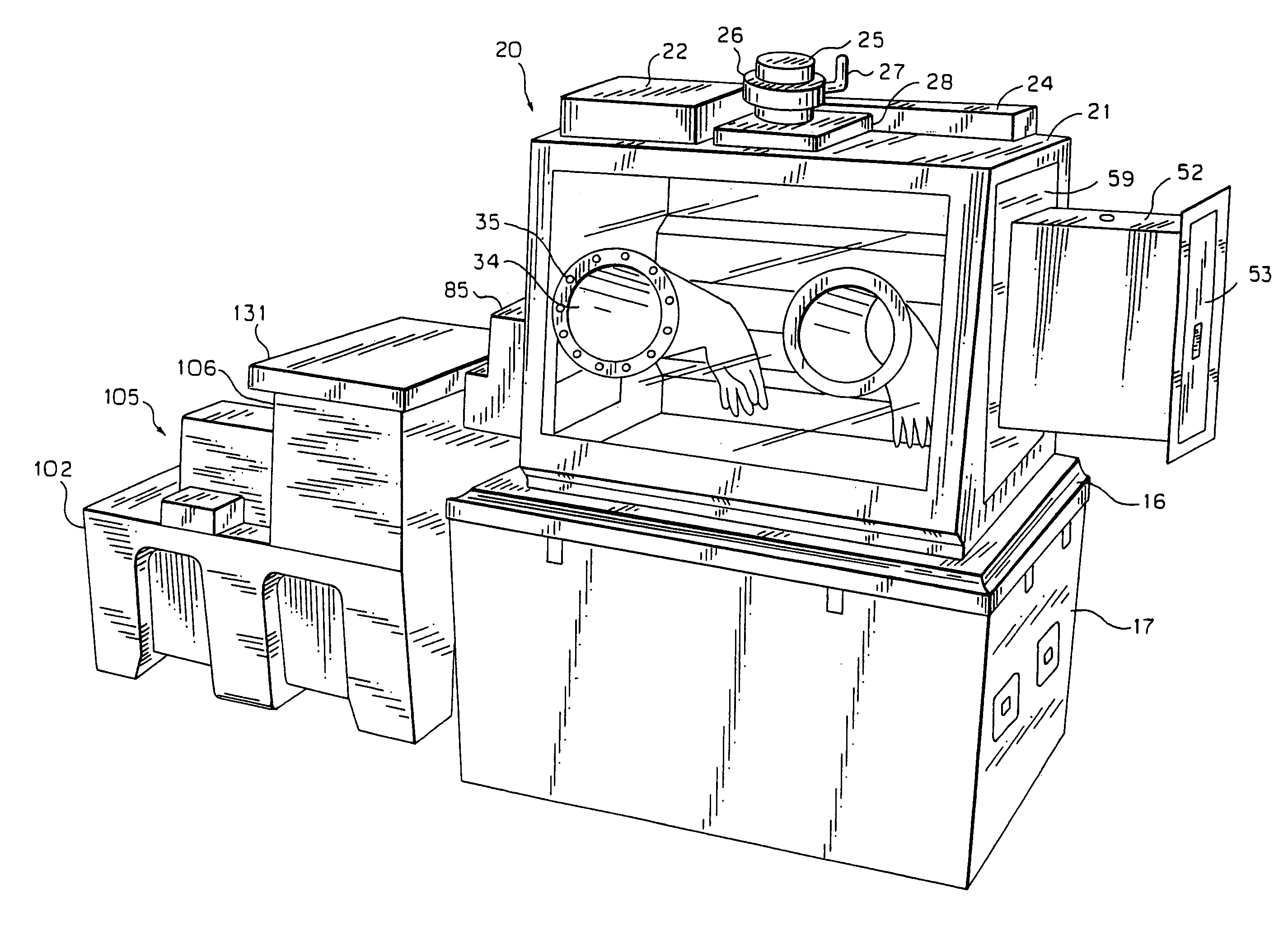
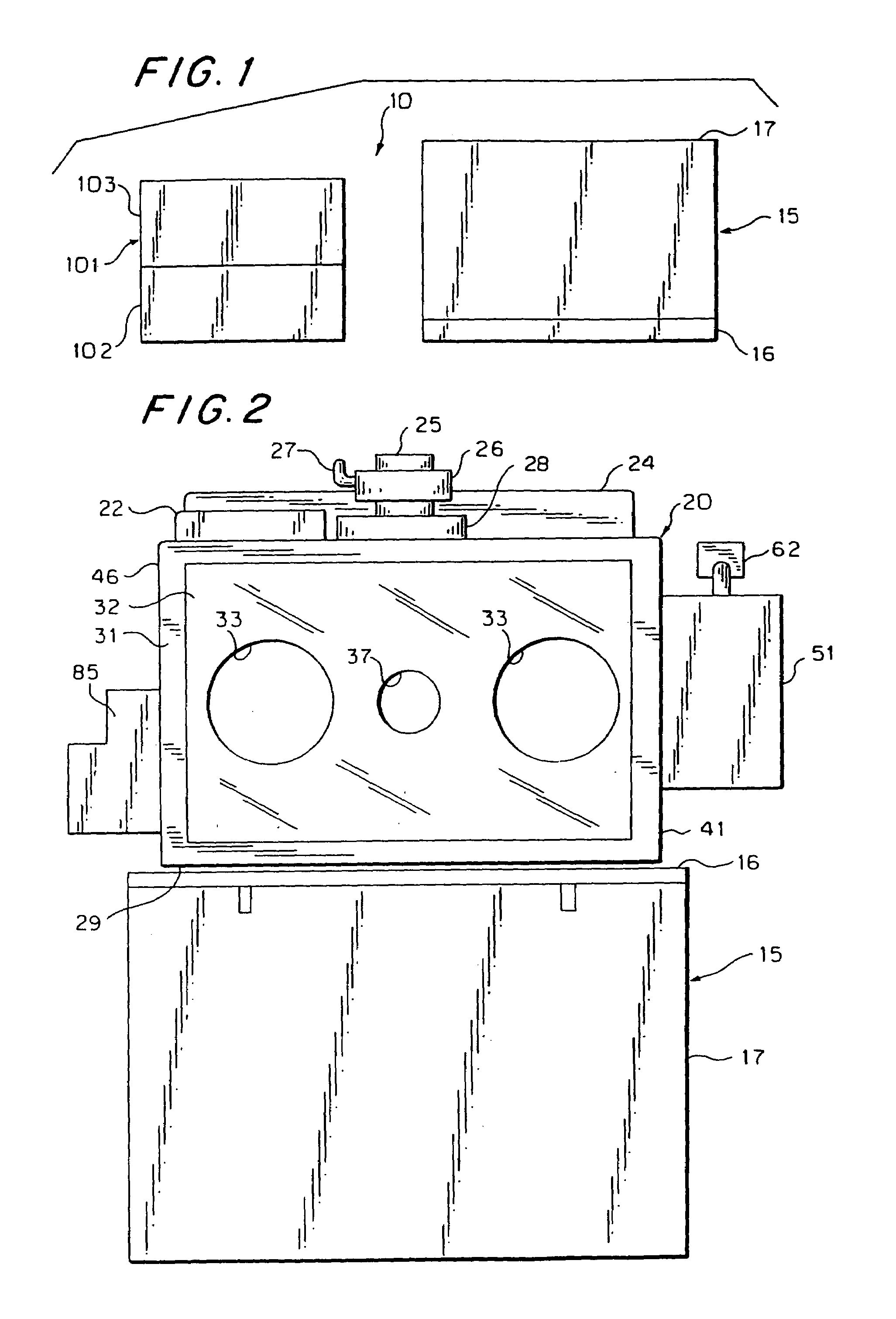
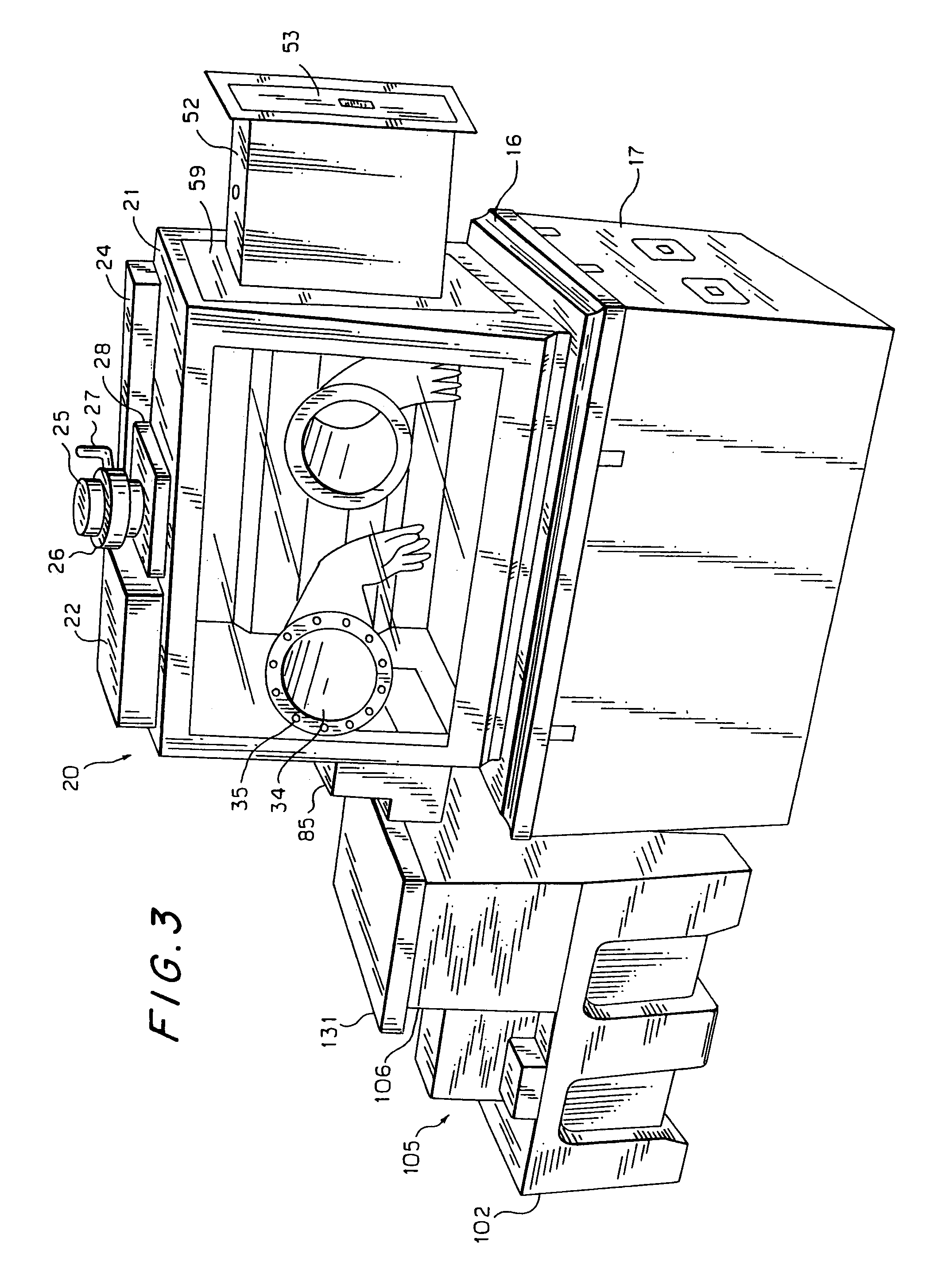
[0036]Referring now to FIG. 1, there is generally shown a self-contained portable containment system 10, comprising a first storage container 15, which holds an isolation chamber or glovebox 20, and a second storage container 101, which holds a filtration or filter system 105. The first storage container 15 comprises a base section 16 and an upper section or cover 17. FIG. 2 illustrates a deployed position where the cover 17 has been lifted off the glovebox unit 20 and then the glovebox 20 and the base 16 have been mounted on the cover 17. As shown in FIG. 1, the second storage container 101 comprises a lower section 102 and a removable upper section 103. During use, the filtration system 105 can remain supported within the lower section 102, as shown in FIGS. 3 and 4. Storage of the glovebox and the filtration system in portable containers allows the devices to be transported to remote locations in a safe and efficient manner.

[0037]FIGS. 1 through 8 generally depict an arrangement ...


PUM


Abstract

A portable containment system includes a glovebox apparatus, a self-contained filter unit, and removable conduits extending therebetween. The glovebox apparatus includes a first module for releasably covering a first sidewall opening. The first module, which has body and flange portions, has a storage position where the body portion is positioned through the first sidewall opening into the glovebox interior and an operative position where the body portion is positioned exterior of the glovebox. The glovebox apparatus includes second modules for releasably covering a second sidewall opening where the second modules are smaller than the first sidewall opening for inserting the second modules into the interior of the glovebox for storage. The filter unit includes a plurality of gas filters, an air pump, and detectors for monitoring the air flow through the system.

Description

CROSS-REFERENCE TO RELATED APPLICATIONS[0001]This application is a division of application Ser. No. 10 / 212,652 filed Aug. 5, 2002, now U.S. Pat. No. 6,715,343, which is a division of application Ser. No. 09 / 777,483, filed Feb. 6, 2001, now U.S. Pat. No. 6,428,122.BACKGROUND OF THE INVENTION[0002]This invention generally relates to environmental containment equipment, and more particularly, to portable containment equipment that can be safely and readily deployed at remote locations.[0003]Environmental accidents, toxic chemical spills, and testing to support treaty verification inspections are examples of situations where chemical and biological testing may be required at remote sites. Investigators at these sites often perform tests and acquire evidence with limited reliable information on the makeup or concentrations of the possible hazardous substances. At these sites, many tests are performed in the open air, or with improvised engineering controls, thereby relying on wind direct...

Claims


Application Information

Patent Timeline
Patent Type & Authority Patents(United States)
IPC IPC(8): B01L1/00B25J21/02
CPCB01L1/50B25J21/02B01L2200/146B01L2300/0681
Inventor HENRY, CHARLES E.HEYL, MONICA J.REUTTER, DENNIS J.
Owner UNITED STATES OF AMERICA THE AS REPRESENTED BY THE SEC OF THE ARMY
Why Eureka
Try Eureka