
Illumination device mountable through an aperture in a clothing object

a technology of illumination device and clothing object, which is applied in the direction of lighting support device, electric lighting with batteries, lighting and heating apparatus, etc., can solve problems such as difficult actuation, and achieve the effect of effective illumination of the scen

Inactive Publication Date: 2009-11-03
KOOLLIGHT
View PDF51 Cites 63 Cited by
  • Summary
  • Abstract
  • Description
  • Claims
  • Application Information

AI Technical Summary

Benefits of technology

[0013]The power source is preferably a pair of 1.5 V AA or AAA batteries, but LED illuminators and LED clusters particularly lend themselves to 3 V lithium coin cells, e.g., type CR2032, CR2430 or CR2450 batteries. This permits direct drive of the LED or LED cluster from the unregulated output of the batteries, simplifying the circuit. Of course, a regulated voltage design could also be employed. Preferably, a voltage-converter or other driver circuit is employed to drive a set of LEDs. This decouples, in part, the drive voltage of the LEDs from that directly available from the power source. Preferably, the drive circuit is integral with the circuit for mounting the LEDs, providing a two wire interface from the power supply to the LED support and driver circuit. Likewise, it is preferred that the subhousing holding the LED support and driver circuit be switched based on an intermittent supply of current through one or both of the supply wires, effecting a switch mechanism.
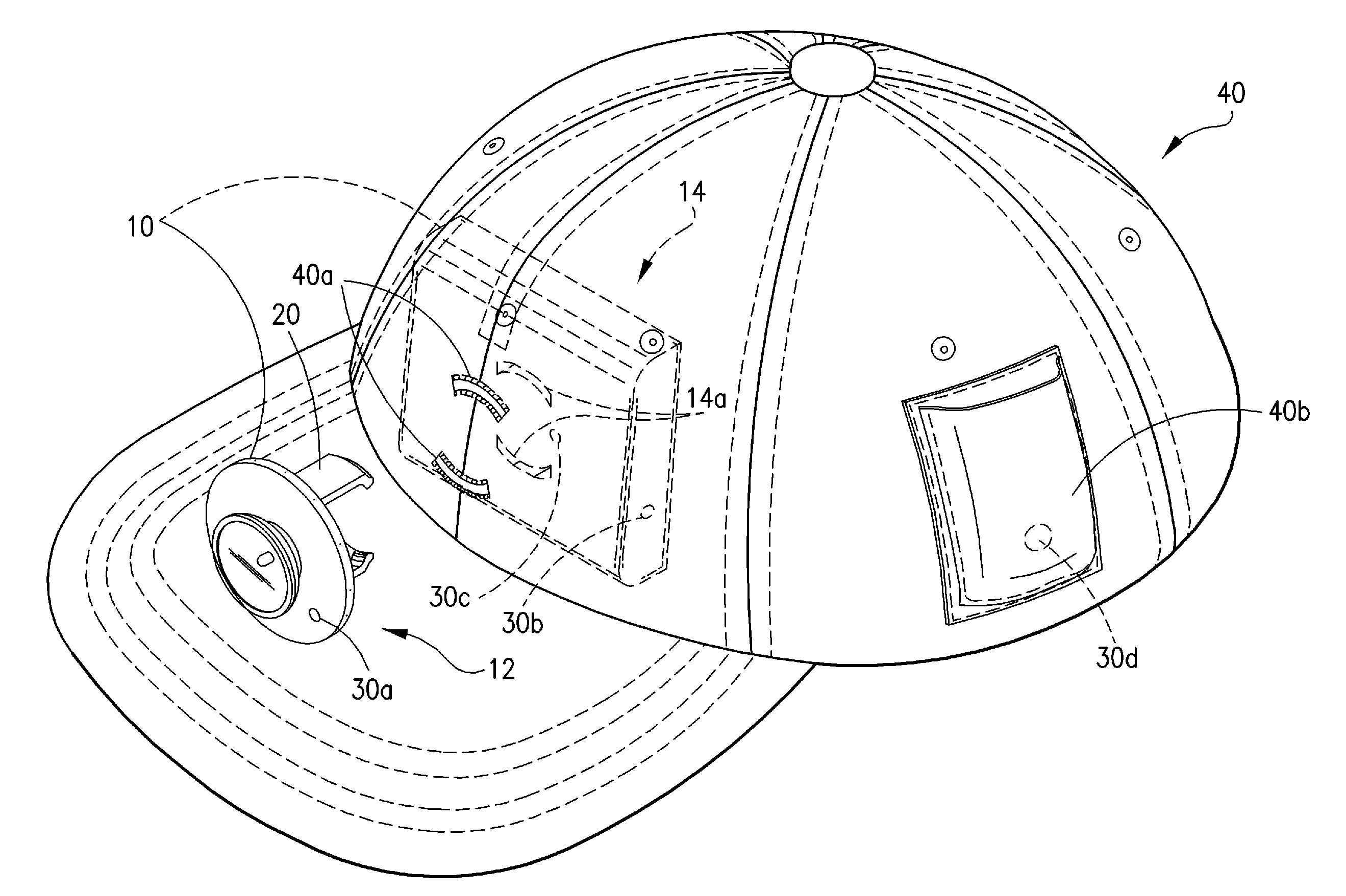
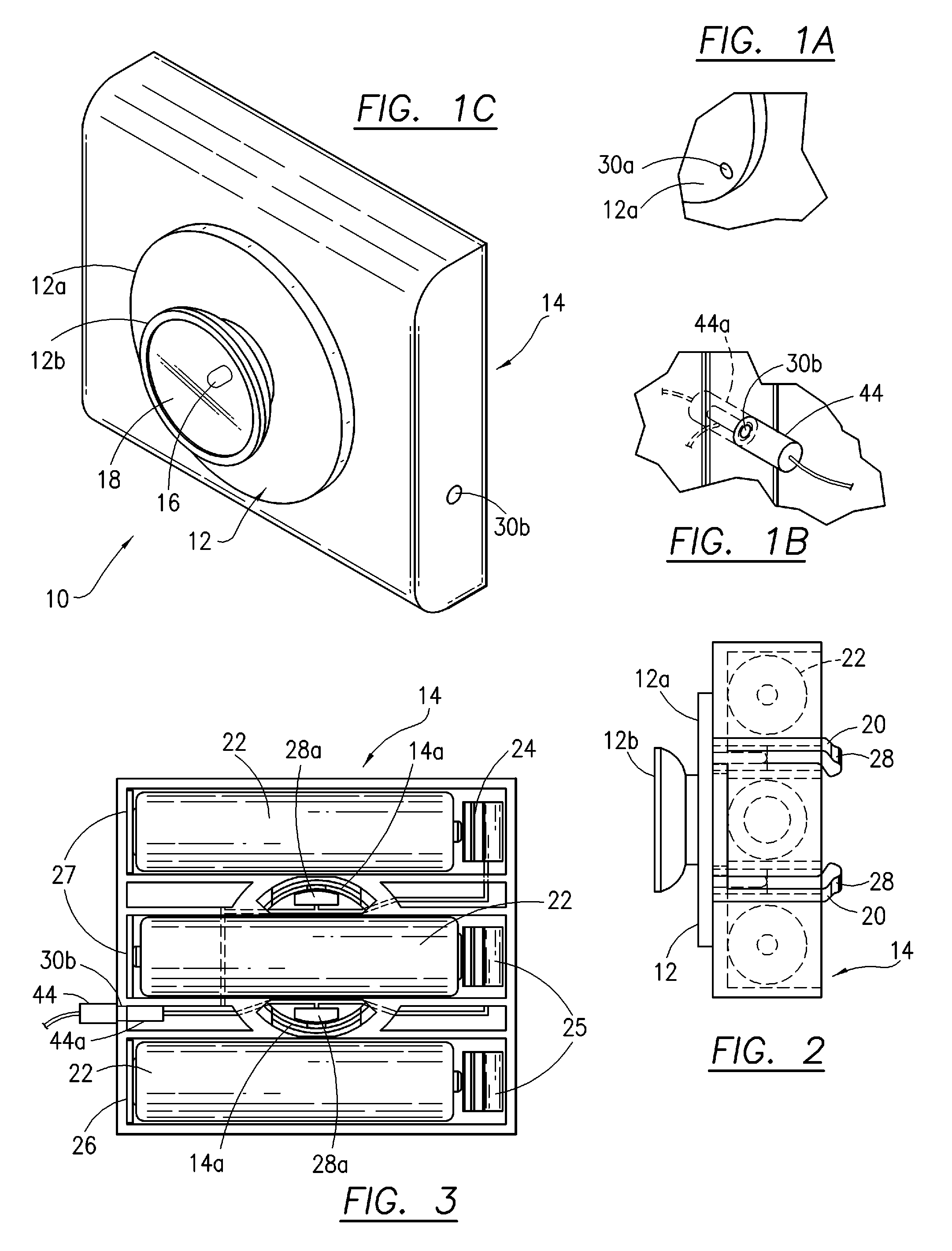
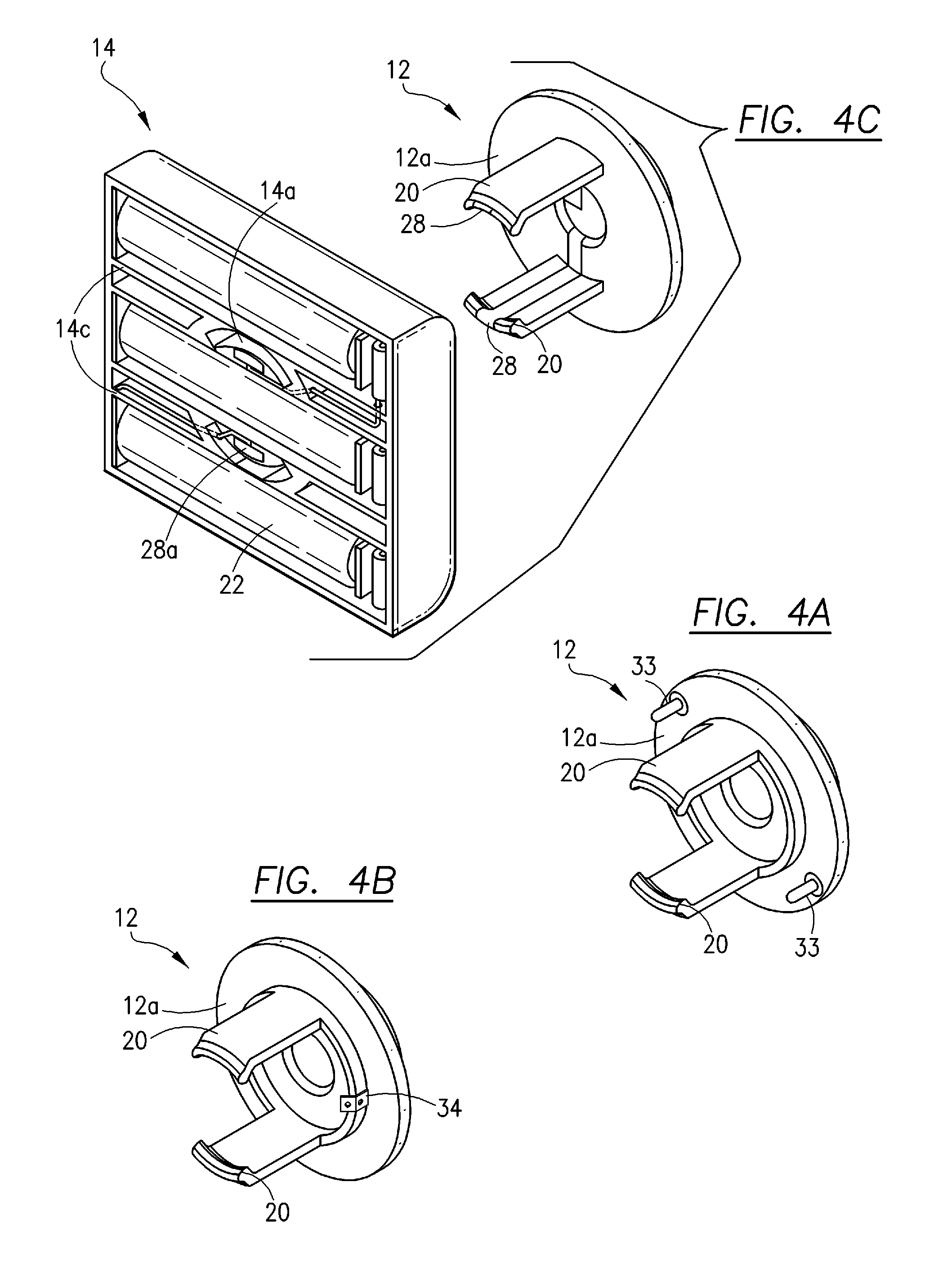
[0015]According to a first embodiment, the illuminator subhousing is provided external to the article of the clothing, with the power supply subhousing provided within (internal to) the article of clothing. In this case, the depth of the power supply subhousing may be only slightly thicker than the thickness of a battery, for example about 0.563 inch, which is reduced from the prior art design according to U.S. Pat. No. 6,932,487, and D426,330, which has increased thickness due to the depth of the illuminator subhousing, e.g., about 0.875 inch. The illuminator subhousing, in this case, has a set of supports that penetrate through the article of clothing, which may be slits reinforced with thread, for example in the manner of buttonholes. The standoffs preferably provide mechanical support for the illuminator subhousing, as well as electrical connection, although the electrical connection may be provided by other means such as a plug type configuration or wire harness. The standoffs are separable from the power supply subhousing, thus permitting removal of the illumination unit from the article of clothing, for example to facilitate cleaning. With this configuration, the external illuminator subhousing may comprise various designs and light colors, and technologies, and indeed, the illuminator may be replaceable separate from the power supply and article of clothing. Since, in contrast to the design of U.S. Pat. No. 6,932,487, and D426,330, the illuminator subhousing does not protrude into the power supply subhousing. This provides for a more efficient design which allows at least one additional battery to be provided if so desired, and / or the power supply subhousing reduced in size. Likewise, eliminating some of the portion of the housing on the inside of the clothing minimizes wearer discomfort. This design can also be used with various sizes of batteries by adjusting the proportions of the power supply subhousing accordingly, the object being to maintain an efficient design in relation to the size and placement of the batteries. In known designs, a clip provided to retain the housing to the clothing, with the clip compressing a textile sheet against the housing. A pair of extensions protrude from the clip body and engage the housing, each extension having a width of about 0.625 inch for a 1.375 inch diameter hole, resulting in a noticeable arch. A preferred embodiment reduces the width of the extensions for connecting the housing to the clothing to about 0.375 inch, which reduces the arch depth, and enables the batteries to be placed closer together, further minimizing the space required by the sub-housing. If desired, the distance between extensions can be reduced, further increasing the efficiency of space in the power supply subhousing. Because the illuminator subhousing does not protrude into the power supply subhousing, a hole is no longer necessary and the extensions can be passed through be slits as indicated above.
[0017]According to another implementation of the invention, a camera and / or a microphone may be mounted in addition to, or in place of the illuminator, or these may be concealed within the illuminator casing. This camera and / or microphone units may be wireless for sending and remotely saving video and audio taken by the wearer, or may be saved within a memory module located within the illuminator casing, power supply casing or disposed in a location on the article of clothing or hat. The illuminator is preferably aligned with the lens axis, so that the illuminator effectively illuminates the scene. In some cases, the illumination may be infrared, and the camera responsive to infrared.

Problems solved by technology

Therefore, the illumination control is preferably not on a hidden portion of this compartment, since this may make actuation difficult.

Method used


Image

  • Illumination device mountable through an aperture in a clothing object
  • Illumination device mountable through an aperture in a clothing object
  • Illumination device mountable through an aperture in a clothing object

Examples


Embodiment Construction

[0040]Referring now to the drawings, FIGS. 1A through 9 depict a preferred embodiment and variants thereof, wherein the illuminator casing and the power supply casing are separate from each other. The illuminator casing is located on the outside of the article of clothing or hat, and the power supply casing is located on the inside of the article of clothing. This preferred set of embodiments allows use of a power supply casing that has an efficient design and low profile, thereby providing comfort for the wearer. The illuminator casing and power supply casing are attached together through one or more apertures in the article of clothing or hat. It is also possible to provide an embodiment wherein the a thin wire extends from the power supply casing inside the article, and the illuminator casing external, without forming an aperture. A strong magnet may then be used to sandwich the article of clothing and support the illuminator casing in position, against another magnet or a steel ...


PUM


Abstract

A light adapted to be attached to an article of clothing, comprising a power supply casing, an illuminator casing, having therein an illuminator adapted to emit a beam of light when electrically powered, said power supply casing and illuminator casing being attachable and detachable to the article of clothing through an aperture by means of at least one extension, said at least one extension providing mechanical interconnection and a clamping force between said internal casing and a clamp to retain the article of clothing therebetween.

Description

BACKGROUND OF THE INVENTION[0001]1. Field of the Invention[0002]This invention relates to an illumination device which is mountable through an aperture in a sheet of material, which, for example, is an object of clothing, such as a hat, shirt or jacket, for example an incandescent lamp, light emitting diode (LED) or an array of LEDs within a housing which may be mounted through a hole in an article of clothing, to provide lighting for a wearer.[0003]2. Description of Related Art[0004]Portable lights have been used in the past with garments, including lights attached to headgear or other garment articles for illumination purposes. Based on its usage such as in a hat (or on a garment), the size, weight, weight distribution and access to the battery pack become characteristics that affect the overall usability of the portable light. See, U.S. D426,330; D127,785; D176,073; D214,943; D238,958; D275,523; D296,719; D300,868; D318,338; D320,667; D337,838; D362,080; D373,433; U.S. Pat. No. 2...

Claims


Application Information

Patent Timeline
IPC IPC(8): F21V21/08
CPCA42B1/244F21V21/0885F21L4/00F21V21/084
Inventor LAGASSEY, PAUL J.
Owner KOOLLIGHT
Learn More