Electric jigsaw capable of improved illumination of workpieces

Inactive Publication Date: 2006-12-26
MAKITA CORP
View PDF33 Cites 36 Cited by
  • Summary
  • Abstract
  • Description
  • Claims
  • Application Information

AI Technical Summary

Benefits of technology

[0009]In view of the above-identified problems, an important object of the present invention is to provide an reciprocating cutting tool or jigsaw capable

Problems solved by technology

While the foregoing arrangement achieves its intended objective, it is not free from certain problems and inconveniences that reduce the utility of the device.
For example, since the front coupler guard is adapted to move between the two positions, an illuminant cannot be installed in the guard.
However, if an illuminant is disposed directly above the front guard, the light from the illuminant would be blocked by the coupler guard and not reach the workpiece.
Accordingly, the housing must be specially redesigned, for example, to accommodate an illuminant ab

Method used


Image

  • Electric jigsaw capable of improved illumination of workpieces
  • Electric jigsaw capable of improved illumination of workpieces
  • Electric jigsaw capable of improved illumination of workpieces

Examples


Embodiment Construction

[0039]Preferred embodiment of the present invention will be described hereinafter with reference to the attached drawings.

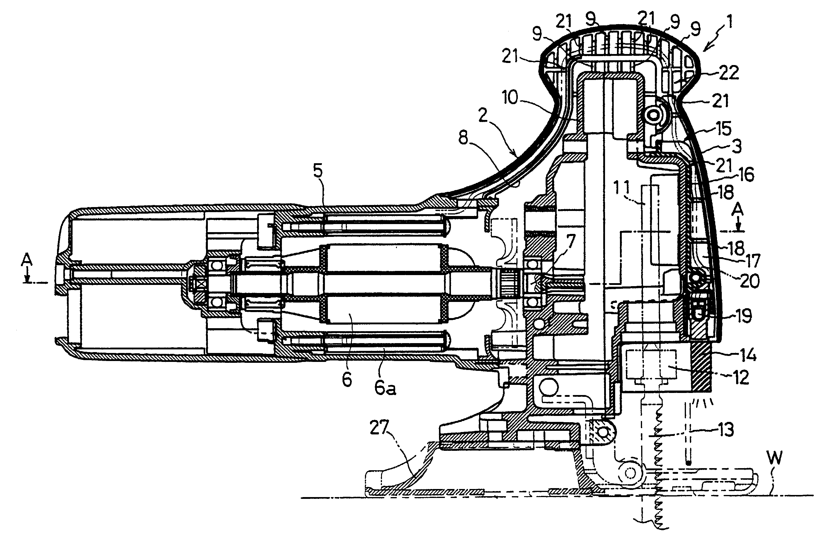
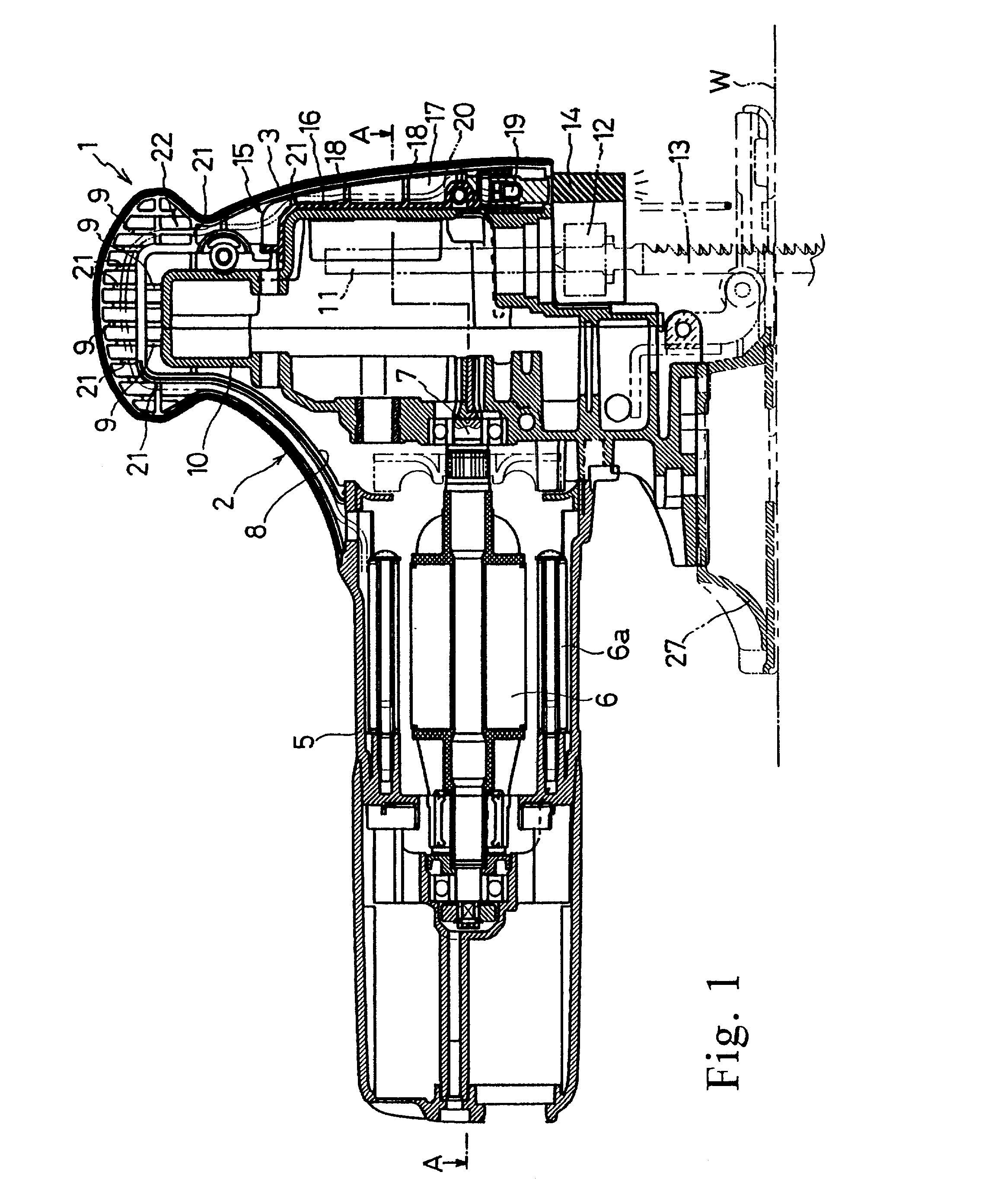
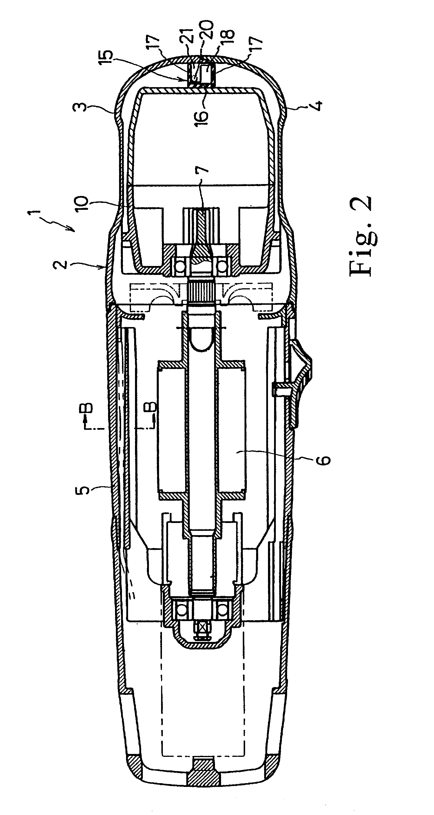
[0040]FIG. 1 is a vertical cross-sectional view of an electric power jigsaw 1 in accordance with the present invention. The jigsaw 1 includes a base plate 27, a pair of split-half clamshells 3 and 4 fitted together to form a main housing 2 mounted on the base plate 27, and an approximately cylindrical motor housing 5 which is connected to and projects from the rear wall of the main housing 2 (as used herein, the term rear is intended to indicate the left side of FIG. 1). Additionally to FIGS. 1 and 2, the motor housing 5 contains a horizontally oriented motor 6 with a field element 6a and an armature spindle 7 which projects therefrom into a gear housing 10 within the main housing 2 and is coupled to reduction gears and a motion converter mechanism such as a cam (neither shown). The mechanism converts the rotational motion of the motor to a linearly reciprocating...


PUM

PropertyMeasurementUnit
Areaaaaaaaaaaa
Transparencyaaaaaaaaaa

Abstract

An electric jigsaw (1) includes a main housing (2) containing a gear housing (10), a reciprocating rod (11) vertically projecting from within the gear housing, a saw blade (13) coupled to the rod via a coupling ring (12), and a transparent synthetic resin guard (14) provided at the lower front end of the main housing and the gear housing (10). The transparent guard includes a vertical optical path therethrough and is attached to the gear housing in such a manner as to be horizontally rotatable between a protective position for covering the coupling ring and an open position for exposing the coupling ring. Additionally included in the jigsaw is an insulating cover (15) assembled to the gear housing (10) within the main housing (2) and a downward oriented light-emitting diode (19) disposed at the bottom end of the insulating cover (15) directly above the transparent guard (14) when the guard is in its protective position. The light from the LED is transmitted through the front guard along the optical path, illuminating a workpiece (W) immediately forward of the blade without significant scattering or diffusion.

Description

[0001]This application claims priority on Japanese Patent Application No. 2001-145417 filed on May 15, 2001, the contents of which are incorporated herein by reference.BACKGROUND OF THE INVENTION[0002]1. Field of the Invention[0003]The present invention generally relates to electric power tools. More particularly, the present invention relates to a jigsaw including a housing and a blade which projects downward from the front portion of the housing and reciprocates vertically for cutting workpieces.[0004]2. Description of the Related Art[0005]A typical electric jigsaw includes a housing, a motor encased within the housing, a vertically oriented rod or blade holder shaft provided at the front of the housing and driven by the motor so as to make reciprocating motion, and a blade attached to the bottom end of the reciprocating rod via a coupler. Such a jigsaw further includes at the lower front end of the housing a front guard that covers the coupler without being in contact with the co...

Claims


Application Information

Patent Timeline
IPC IPC(8): B23B49/00B23D49/14B23D49/16B23D51/00B25F5/02B27B19/02
CPCB23D49/162B23D51/00B25F5/021
Inventor KONDO, MASAKISAKABE, ICHIOHIRABAYASHI, SHINJI
Owner MAKITA CORP
Why Eureka
Try Eureka