
Utility helment with integrated lighting system

a technology of lighting system and welding helmet, applied in the field of welding helmet adaption, can solve the problems of poor or inefficient lighting of work areas, poor ambient lighting of many work environments, inability of workers to see well in the workspace, etc., and achieve the effects of reducing workspace errors or accidents, improving work quality results, and efficient and focused

Active Publication Date: 2011-05-05
ROBINSON LEVI JACOB
View PDF5 Cites 40 Cited by
  • Summary
  • Abstract
  • Description
  • Claims
  • Application Information

AI Technical Summary

Benefits of technology

[0010]The present inventor realized in an inventive moment that if, at the point of operation, automated and focused workspace lighting could be caused to illuminate a workspace in an efficient and focused manner, significant reduction in workspace errors or accidents might result. The inventor therefore constructed a unique lighting system applicable to utility helmets such as welding helmets that allowed for efficient illumination of immediate workspace areas in the environment, but constrained such illumination to areas where needed. A significant improvement in work quality results, with no impediment to efficiency of work created.

Problems solved by technology

The problem stated above is that sufficient illumination is desirable for a welding environment, but many of the conventional means for illuminating a workspace, such as building lights, mobile shop lights, or hand-held lights, also create poor or inefficiently lighted areas.
Many work environments are poorly illuminated with ambient lighting, one by-product of which is an abundance of work-related errors or accidents resulting from the inability of the worker to see well in the workspace.
Most such environments employ some form of shop or building lighting, but a good number of environments may be completely unlighted requiring mobile lighting to illuminate the workspaces in the environment.

Method used


Image

  • Utility helment with integrated lighting system
  • Utility helment with integrated lighting system
  • Utility helment with integrated lighting system

Examples


Embodiment Construction

[0030]The inventor provides a unique welding shield with integrated lighting and lighting control system. The present invention will be described in enabling detail using the following examples, which may describe more than one relevant embodiment falling within the spirit and scope of the present invention.

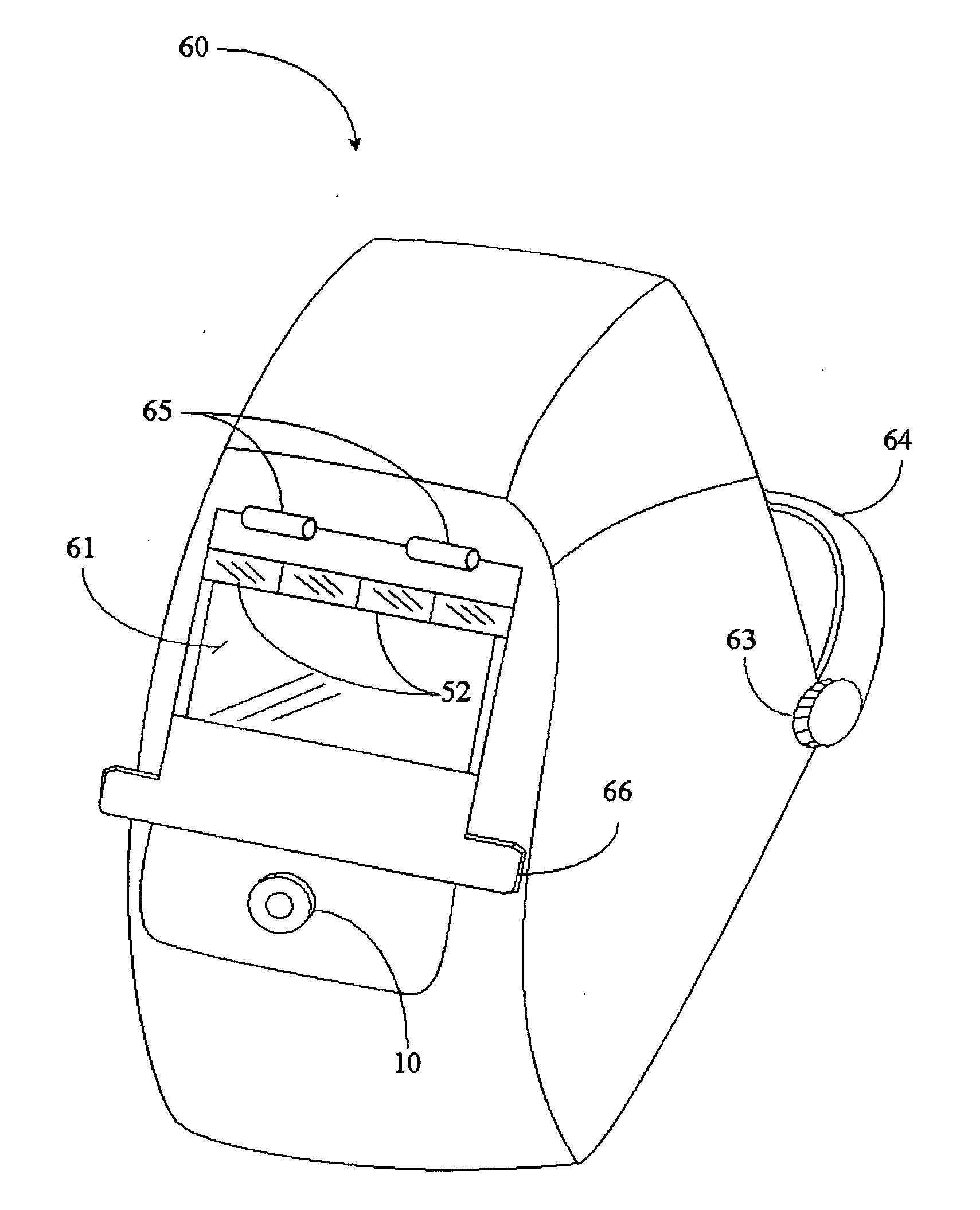
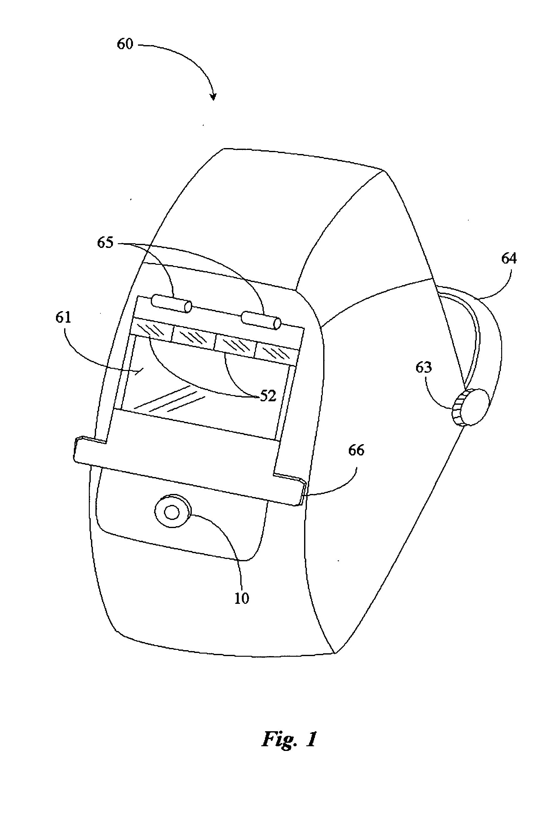
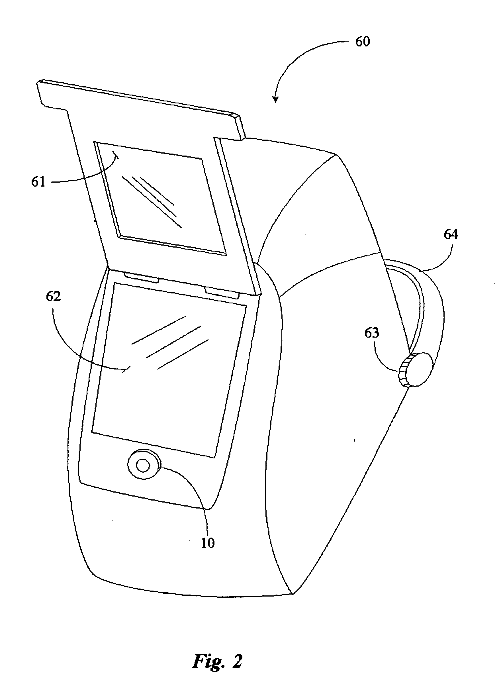
[0031]FIG. 1 is a perspective view of a welding shield 60 according to an embodiment of the present invention. Welding shield 60 may also be referred to herein as a face shield or helmet-face shield without departing from the spirit and scope of the present invention. The term welding shield is a well-known industry term for a welding helmet.

[0032]In this example, shield 60 includes a welding shield lens 61 attached to shield 60 by way of one or more hinges 65. Shield lens 61 may be an auto-darkening lens, a shaded lens, or a transparent protective viewing lens without departing from the spirit and scope of the present invention. Shield lens 61 is in the closed position. Lens 61 ...


PUM


Abstract

A welding shield includes a durable shell body having a front viewing window pivotally attached to a headband, a welding shield lens attached to the shell body covering the front viewing window of the shell body, a first light source disposed to the front area of the shell body, a second light source disposed to the front area of the headband, and at least one control device for controlling the light sources.

Description

CROSS-REFERENCE TO RELATED DOCUMENTS[0001]The present invention claims priority to a U.S. provisional patent application Ser. No. 61 / 280,382 entitled SAFETY HELMET WITH LIGHTING SYSTEM filed on Nov. 3, 2009 disclosure of which is incorporated herein in its entirety at least by reference.BACKGROUND OF THE INVENTION[0002]1. Field of the Invention[0003]The present invention is in the field of safety gear including workplace utility helmets and pertains particularly to methods and apparatus for adapting a welding helmet, also referred to as a welding shield with a controlled lighting system that may be operated in automated fashion.[0004]2. Discussion of the State of the Art[0005]In many industries like manufacturing and construction, welding is a common practice. Welders wear welding helmets, sometimes referred to as welding shields or face shields, during the course of their work. Generally speaking, a welding shield is constructed to pivot about the workers head and typically has two...

Claims


Application Information

Patent Timeline
Patent Type & Authority Applications(United States)
IPC IPC(8): H05B37/00A61F9/06
CPCA61F9/064F21Y2113/005H05B37/0227F21K9/30F21V21/084F21Y2101/02F21K9/58F21V14/025F21V23/003F21V23/0414F21V33/0064F21W2131/402F21V23/04F21V23/0492F21V33/008A61F9/067F21V33/00F21Y2115/10H05B47/105F21K9/20F21K9/65F21Y2113/13
Inventor ROBINSON, LEVI JACOB
Owner ROBINSON LEVI JACOB
Learn More