Valve tester suspension enhancements

a technology of suspension and valve, which is applied in the direction of valve operating devices/release devices, instruments, transportation items, etc., can solve the problems that devices do not present a suitable solution for suspending valve testing or exercising, and achieve the effect of reducing the potential for injury or accident and increasing the efficiency of the process of testing underground valves

Active Publication Date: 2008-02-26
HURCO TECH
View PDF46 Cites 37 Cited by
  • Summary
  • Abstract
  • Description
  • Claims
  • Application Information

AI Technical Summary

Benefits of technology

[0009]One advantage of the valve tester suspension assembly of the present invention is that the task of operating or testing or exercising a valve is in most cases converted from a multiple person job to a job that can be performed by a single worker.
[0010]Another advantage of the valve tester suspension assembly of the present invention is that precise positioning of a vehicle carrying the invention is not necessary, and the efficiency of the process of testing underground valves is thereby increased.
[0011]Yet another advantage of the valve tester suspension assembly of the present invention is that not only is the task of testing the valve converted from a two person job into a one person job, but the physical requirements for the person performing the task is reduced, thus reducing the potential for injury or accidents.

Problems solved by technology

While these devices fulfill their respective, particular objectives and requirements, it is believed that these devices do not present a suitable solution for suspending a valve testing or exercising apparatus is a manner that facilitates the testing process by a single person to that easily adapts to variations in the orientations or positions of the valves often encountered under real world conditions.

Method used


Image

  • Valve tester suspension enhancements
  • Valve tester suspension enhancements
  • Valve tester suspension enhancements

Examples


Embodiment Construction

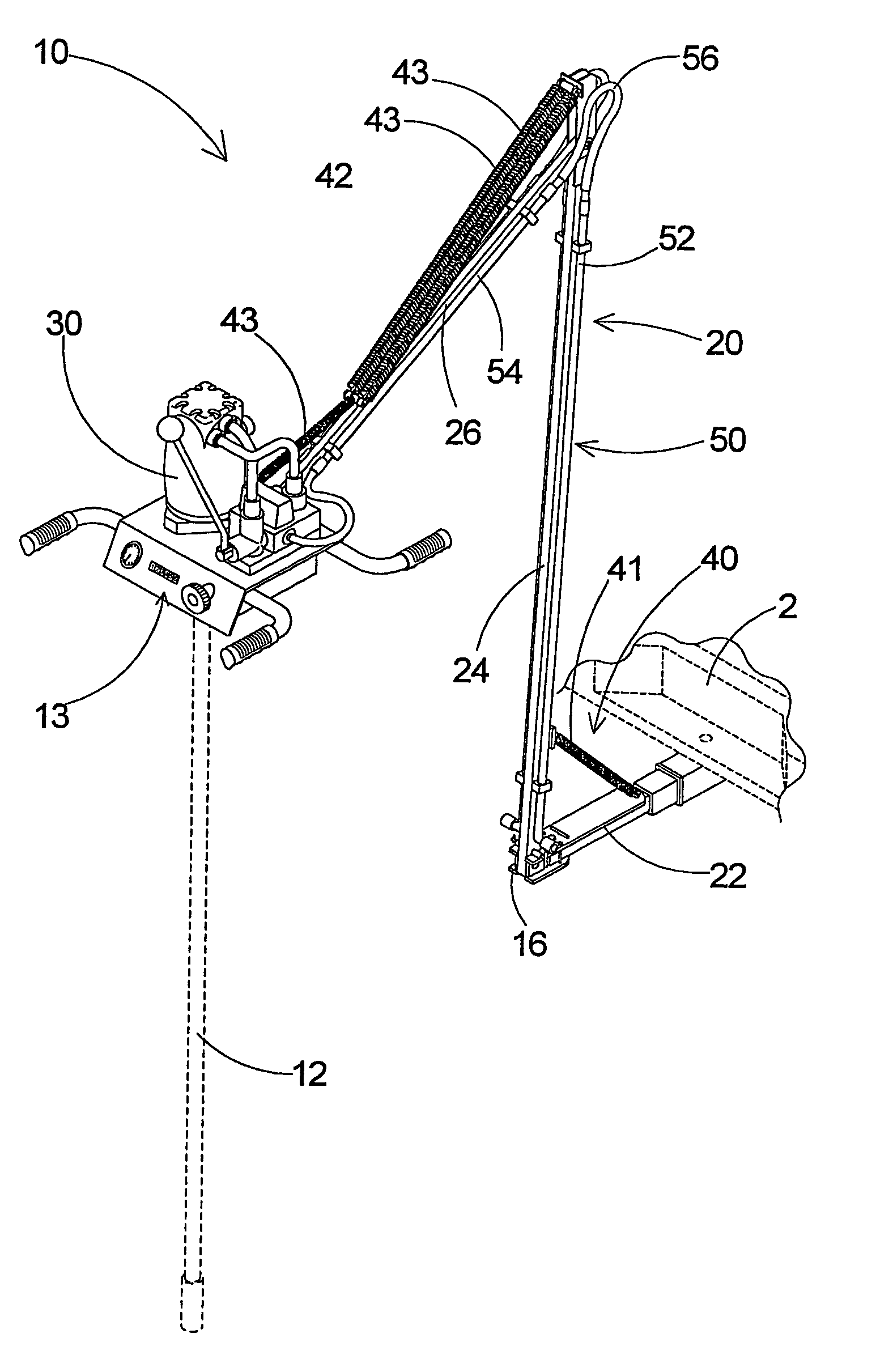
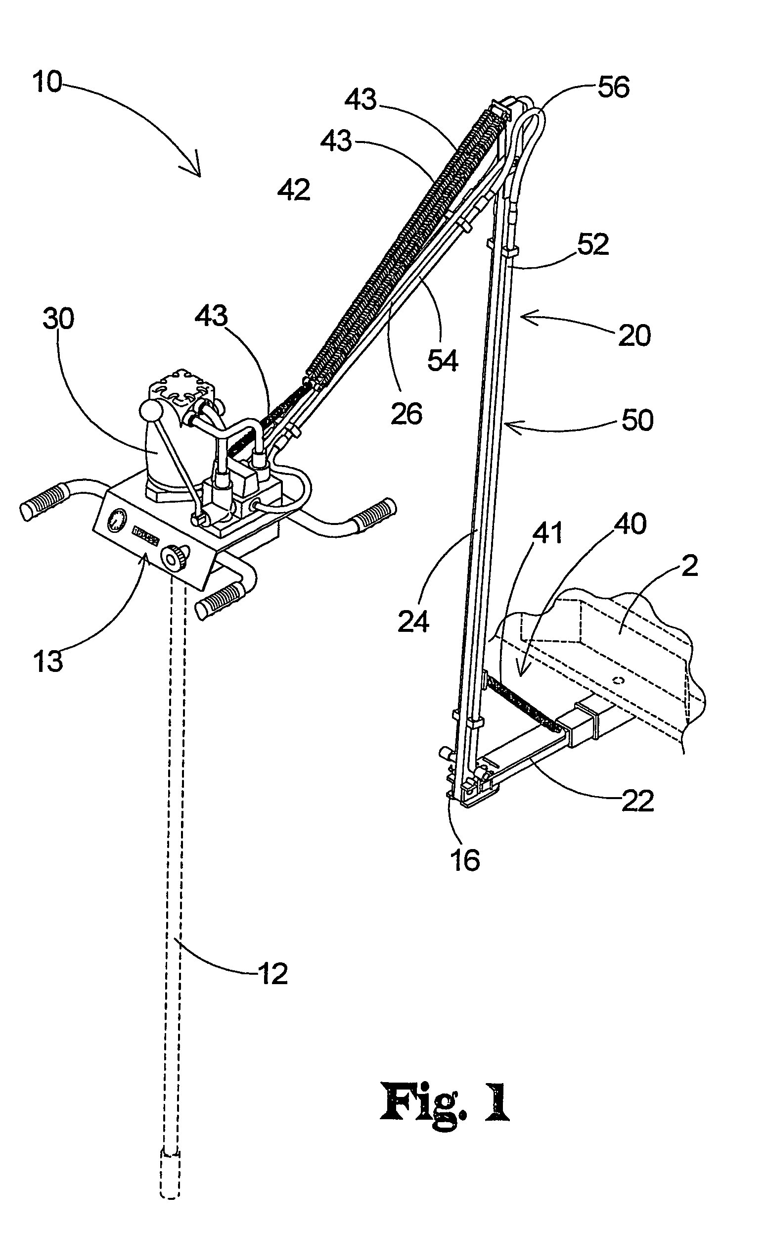
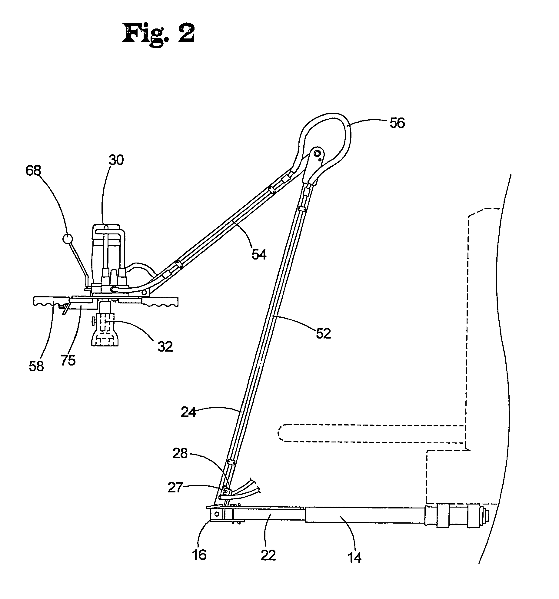
[0029]With reference now to the drawings, and in particular to FIGS. 1 through 15 thereof, a new valve tester suspension assembly embodying the principles and concepts of the present invention and generally designated by the reference numeral 10 will be described.

[0030]As best illustrated in FIGS. 1 through 12, the valve tester suspension assembly 10 generally comprises an articulated arm assembly 20 designed for coupling to a vehicle 2. A hydraulically powered rotating assembly 30 is pivotally coupled to the arm assembly 20 such that the rotating assembly 30 is positionable in a substantially horizontal orientation at a selectable position in a three dimensional space adjacent the vehicle 2. A shaft 12 is provided having a first end 13 operationally couplable to the rotating assembly 30 for rotating the shaft 12. Typically, the shaft has a receiving portion having a geometric cross-sectional shape for receiving a protrusion 32 rotated by the rotating assembly 30. An adapter 28 is a...


PUM

PropertyMeasurementUnit
distanceaaaaaaaaaa
lengthaaaaaaaaaa
lengthaaaaaaaaaa

Abstract

A valve tester assembly is disclosed that includes an articulated arm assembly having a first end and a second end, with the second end of the articulated arm assembly being movable away from and toward the first end such that when the first end of the articulated arm assembly is connected to a vehicle, the second end of the articulated arm assembly is movable away from and toward the vehicle. The assembly includes a rotation mechanism that is mounted on the articulated arm assembly toward the second end of the articulated arm for rotating a shaft for exercising a valve. The assembly further includes a moving mechanism that is mountable on a vehicle for moving the first end of the articulated arm assembly away from and towards the vehicle.

Description

REFERENCE TO RELATED APPLICATION[0001]This application is a continuation-in-part of my patent application Ser. No. 10 / 351,636, filed Jan. 24, 2003.BACKGROUND OF THE INVENTION[0002]1. Field of the Invention[0003]The present invention relates to suspension assemblies and more particularly pertains to a new valve tester suspension assembly for allowing one person to perform the tasks necessary to test the underground valves.[0004]2. Description of the Prior Art[0005]The use of suspension assemblies is known in the prior art. U.S. Pat. No. 6,155,359 describes a vehicle mounted post hole digger. Another type of suspension assemblies is U.S. Pat. No. 4,869,002 and U.S. Pat. No. 5,540,006 each disclose a hydraulically operated digging arm attached to a vehicle. U.S. Pat. No. 4,883,249 discloses a counterbalancing mechanism for a constant force or load. U.S. Pat. No. 5,560,130 discloses a trenching apparatus pivotally mounted to a tractor. U.S. Pat. No. 5,746,404 discloses a wire and pulley...

Claims


Application Information

Patent Timeline
Patent Type & Authority Patents(United States)
IPC IPC(8): F16K37/00F16K31/02
CPCF16K31/46F16K37/0083G01D11/30B60R11/06B60R2011/004Y10T29/49826B60R2011/0087B60R2011/0084Y10T137/6855
Inventor HURLEY, LYNDON J.
Owner HURCO TECH
Why Eureka
Try Eureka