Illuminated stripe and illuminated stripe system

a technology of illumination stripe and stripe, which is applied in the direction of lighting protection devices, lighting heating/cooling arrangements, cold cathode manufacturing, etc., can solve the problems of complex and costly production of coated stripe markings or stripes that contain surfaces coated with phosphorized substances, and the light is often not sufficient to illuminate the phosphorized surface adequately, so as to improve durability, reliability and luminosity of light sources, the stripe structure can be kept simple and robust, and the effect o

Active Publication Date: 2014-02-06
MARMILS OY
View PDF4 Cites 35 Cited by
  • Summary
  • Abstract
  • Description
  • Claims
  • Application Information

AI Technical Summary

Benefits of technology

[0021]The solution of the invention has many important advantages. In the solution of the invention, the casing part of the illuminated stripe is no longer used only as a protective structure but it has further capabilities. The further capabilities are be introduced to the illuminated stripe by including first substance and second substance to the casing part. These capabilities can be added to the stripe of the present invention in such a way that the structure of the stripe can be kept simple and robust. These capabilities can enable certain functions or change the visual appearance of the illuminated stripe, e.g. for guiding or decorative use. The most essential benefits of the method of production of the invention include its simplicity and operating reliability, which enables significantly more profitable production when compared to prior art methods. Also production of the illuminated stripe according to this invention is less complex than with the prior art methods because there are no adhesion problems and no need for additional painting process or extra elements to be attached to the illuminated stripe.
[0022]The solution according to the embodiment where first substance is heat transferring substance and second substance is light storing substance has also many important advantages. The heat transferring substance is able to transfer the heat produced by the light sources away from the light sources, other components and light stripe. This way the durability, reliability and luminosity of the light sources can be improved over the prior art solutions. Also the properties of the casing part can be maintained better at original level when heat is transferred away from the light sources and components and no excess heat is present in the casing part. This creates benefits especially when using high bright LEDs or other light sources or elements that create heat.
[0024]Advantage of an embodiment where second substance is light storing substance is that by means of substance that stores light in the material of the casing part, the illuminated stripe is illuminated also for a certain time after the light sources do not emit light, e.g. owing to an electrical outage, because the casing part of the illuminated stripe which contains a light-storing substance is illuminated with the light sources that are near and in connection with the illuminated stripe when the electric current is in use. In this case the stripe is illuminated better than in prior-art solutions and because the illuminated stripe can be illuminated more effectively and for longer after the extinguishing of the light sources than in prior-art phosphorized stripes or in stripes that are illuminated only by means of an electric current. This is of great advantage in the dark, e.g. in emergency exit routes and this way normal lights are not needed to illuminate the stripe. Another benefit is that the stripe according to this invention needs to pass only photoluminescent approvals and not electric system approvals because the stripe is illuminated also without electricity, Because of this also no battery backed up power supplies are needed and this reduces costs when comparing to the prior art solutions.

Problems solved by technology

The distinguishing of stripes in situations of danger and accident is a problem because the lighting of the stripes typically requires electric current and it would be important to distinguish a stripe also in situations in which electric current is not available for some reason.
This light is often not sufficient to illuminate the phosphorized surface adequately enough for the phosphorized surface to illuminate the stripe brightly enough for long enough in dark conditions.
On the other hand, in a fire situation a predefined emergency exit may be impossible owing to the location of the fire, in which case prior-art solutions might direct in the wrong direction or even towards the fire.
Also production of coated stripe markings or stripes that contain surfaces coated with phosphorized substance is complex and costly and the robustness of the coating doesn't always fulfil all requirements.
These kind of LEDs offer high brightness and luminosity but at the same time they create lot of heat.
The heat production of the light sources of the prior art solutions degrades reliability, durability and luminosity of the light sources.
Also excess heat that is generated in the casing part and not transferred away from the light sources or other components, can damage or affect not only the properties of the light sources but also properties of the casing part so that the effective luminosity of the illuminated stripe is degraded.
Light stripes can also have other components inside the casing part and also these components can suffer from too high temperatures.

Method used


Image

  • Illuminated stripe and illuminated stripe system
  • Illuminated stripe and illuminated stripe system
  • Illuminated stripe and illuminated stripe system

Examples


Embodiment Construction

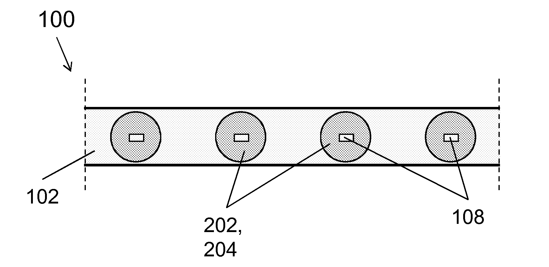
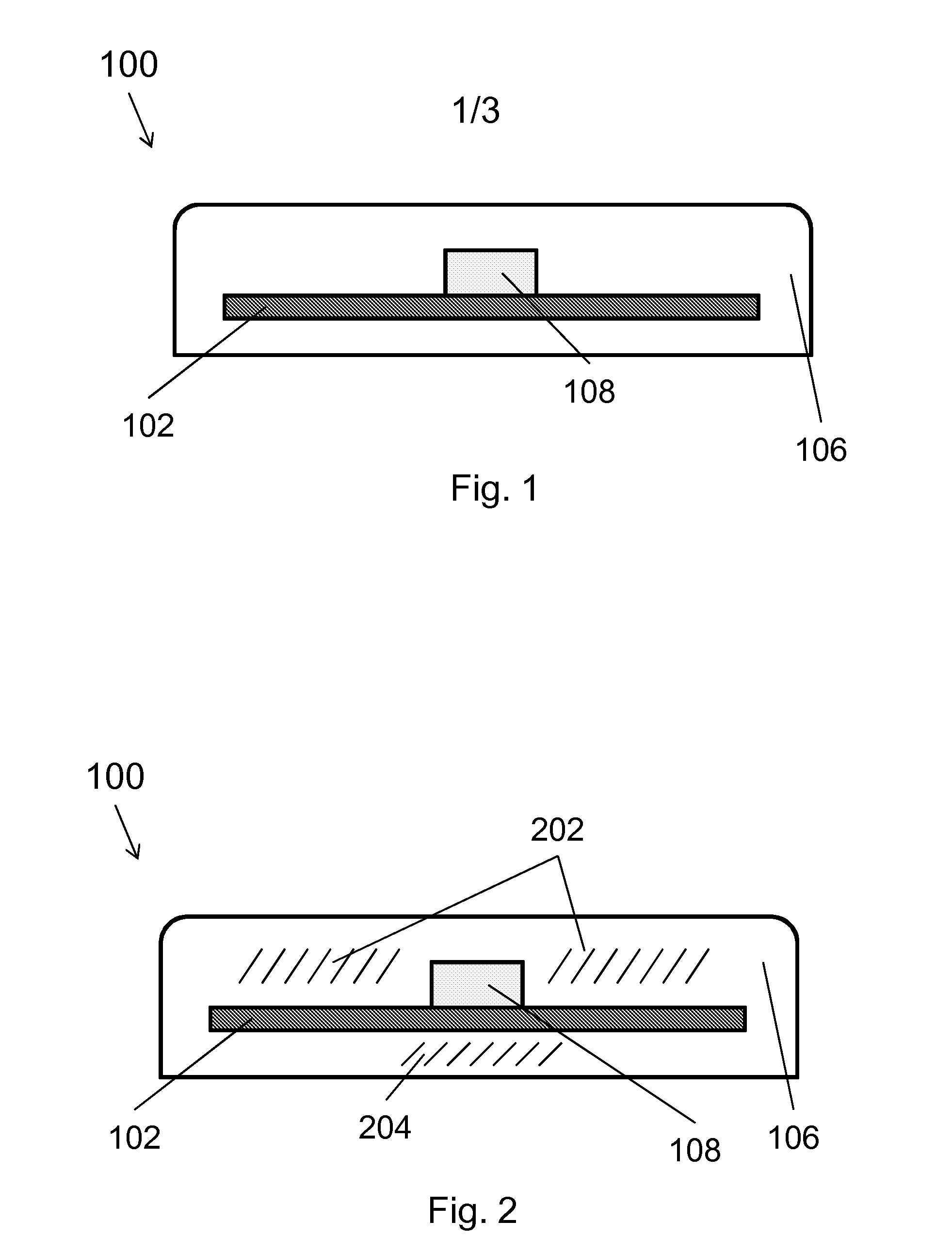
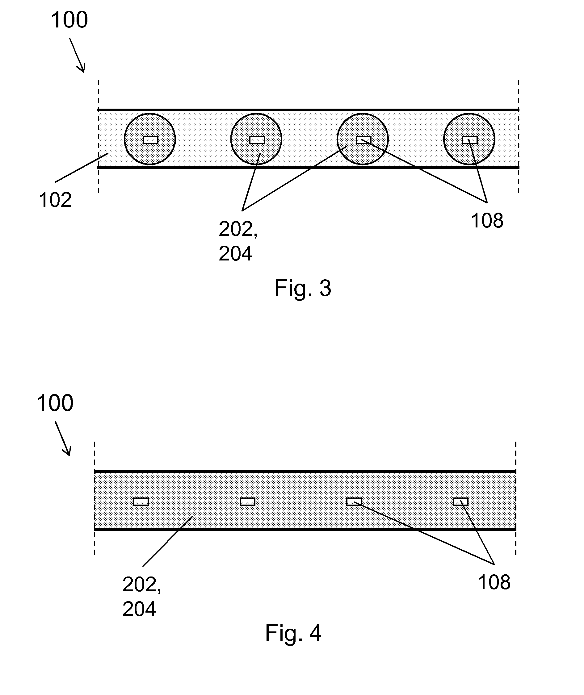
[0031]FIG. 1 presents a cross-section of an example embodiment of an illuminated stripe according to the invention. The illuminated stripe 100 comprises a circuit board 102, to which light sources 108 are connected. An elastic and thin circuit board can be used as the circuit board 102. The light sources 108 can be semiconductor light sources, e.g. LED light sources. The light sources can be LEDs which can be single colour LEDs, e.g. red-, blue-, green-, yellow-, white- or ultra violet (UV)-LEDs or RGB-LEDs, which can provide multiple colours in a single LED light source. The circuit board 102 and the light sources 108 are fitted inside a one-piece casing part 106. Since the casing part 106 is one-piece, the structure of the illuminated stripe 100 is waterproof. Plastic such as PVC, polyurethane, olefin and / or like or some other corresponding material can be used as the material of the casing part 106. The material of the casing part also 106 comprises first and second substance. Th...


PUM


Abstract

An illuminated stripe includes light-emitting light sources and a member for conducting current to the light sources and a casing part. The light sources and / or the member for conducting current to the light sources are at least in part surrounded with the casing part. At least a part of the casing part includes a first substance, and at least a part of the casing part includes a second substance.

Description

[0001]The invention relates to illuminated stripes and to illuminated stripe systems and method of production of illuminated stripe systems.BACKGROUND OF THE INVENTION[0002]Different systems for guiding people in situations of danger and accident, such as in fire situations, to the emergency exits of different buildings, tunnels or vessels are known in the art. These are various visual ways to mark the desired routes, such as lightings of emergency exit routes, or otherwise, e.g. emergency exit routes marked with reflective paint or tape.[0003]One prior-art illuminated stripe is presented in publication FI108106B. It presents a conductor element, which comprises at least an electrically-conductive elongated conductor part, to which a number of components that are consecutive to each other in the longitudinal direction are fixed, e.g. elements that bring about a lighting function or corresponding. The conductor part and the components are surrounded with a casing part.[0004]The disti...

Claims


Application Information

Patent Timeline
Patent Type & Authority Applications(United States)
IPC IPC(8): F21K99/00
CPCF21K9/50H01L25/0753H01L33/56H01L33/64F21V31/00F21V15/01F21V23/0435G08B7/066H01L2924/0002F21V29/87F21S4/24F21Y2103/10F21Y2115/10H05K1/189H05K3/284H05K2201/10106H05K2203/1316H05K2203/1327F21V9/30F21V13/14F21V3/08H01L2924/00F21S4/00
Inventor EGGLETON, RICHARDPITKANEN, TEMMO
Owner MARMILS OY
Why Eureka
Try Eureka