
Fluidized bed reactor arrangement

a technology of reactor arrangement and flue bed, which is applied in the direction of steam superheaters, waste heat treatment, combustion processes, etc., can solve the problems of reducing the possibility of positioning auxiliary equipment, and achieve the effect of strong connection and robust structur

Active Publication Date: 2015-07-28
AMEC FOSTER WHEELER ENERGIA
View PDF27 Cites 0 Cited by
  • Summary
  • Abstract
  • Description
  • Claims
  • Application Information

AI Technical Summary

Benefits of technology

The patent text describes a reactor design that has a unique structure that allows for efficient heat transfer and a simple and robust structure. The design includes an inclined side wall that serves as a partition between the heat exchange chamber and the reaction chamber, which enables direct transfer of supporting forces to the reaction chamber. Additionally, the design ensures that a minimal force component deviating from the vertical direction is generated at the connection, resulting in a strong connection. These technical effects improve the overall performance of the reactor and facilitate its use in various industrial applications.

Problems solved by technology

The support and connection of the heat exchange chamber for solids separated from the reaction chamber to the actual reaction chamber is problematic, especially, in that the heat exchange chamber, horizontally extending far from the reaction chamber, i.e., at least partially outside of the plane of the side wall of the reaction chamber, requires a separate support, which takes up space around the reaction chamber and, thus, diminishes the possibilities to position auxiliary equipment.

Method used


Image

  • Fluidized bed reactor arrangement
  • Fluidized bed reactor arrangement
  • Fluidized bed reactor arrangement

Examples


Embodiment Construction

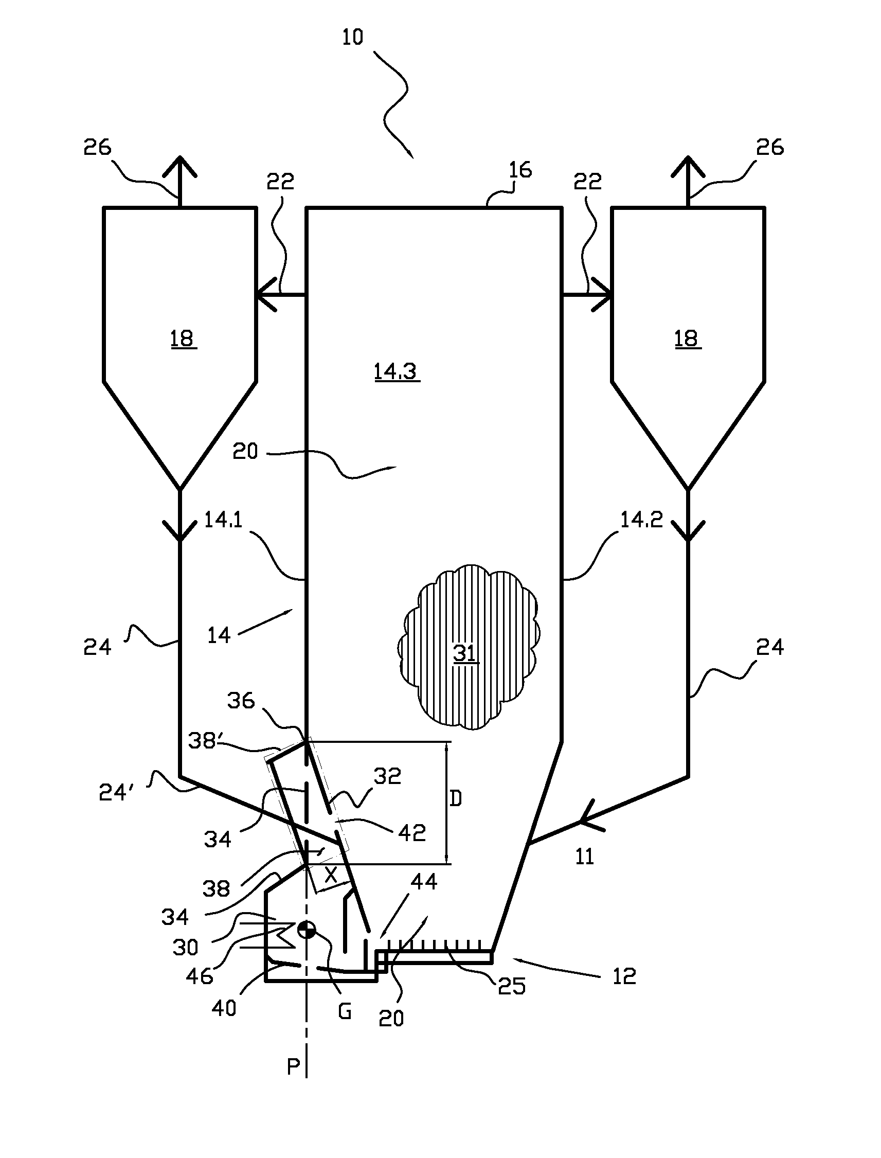
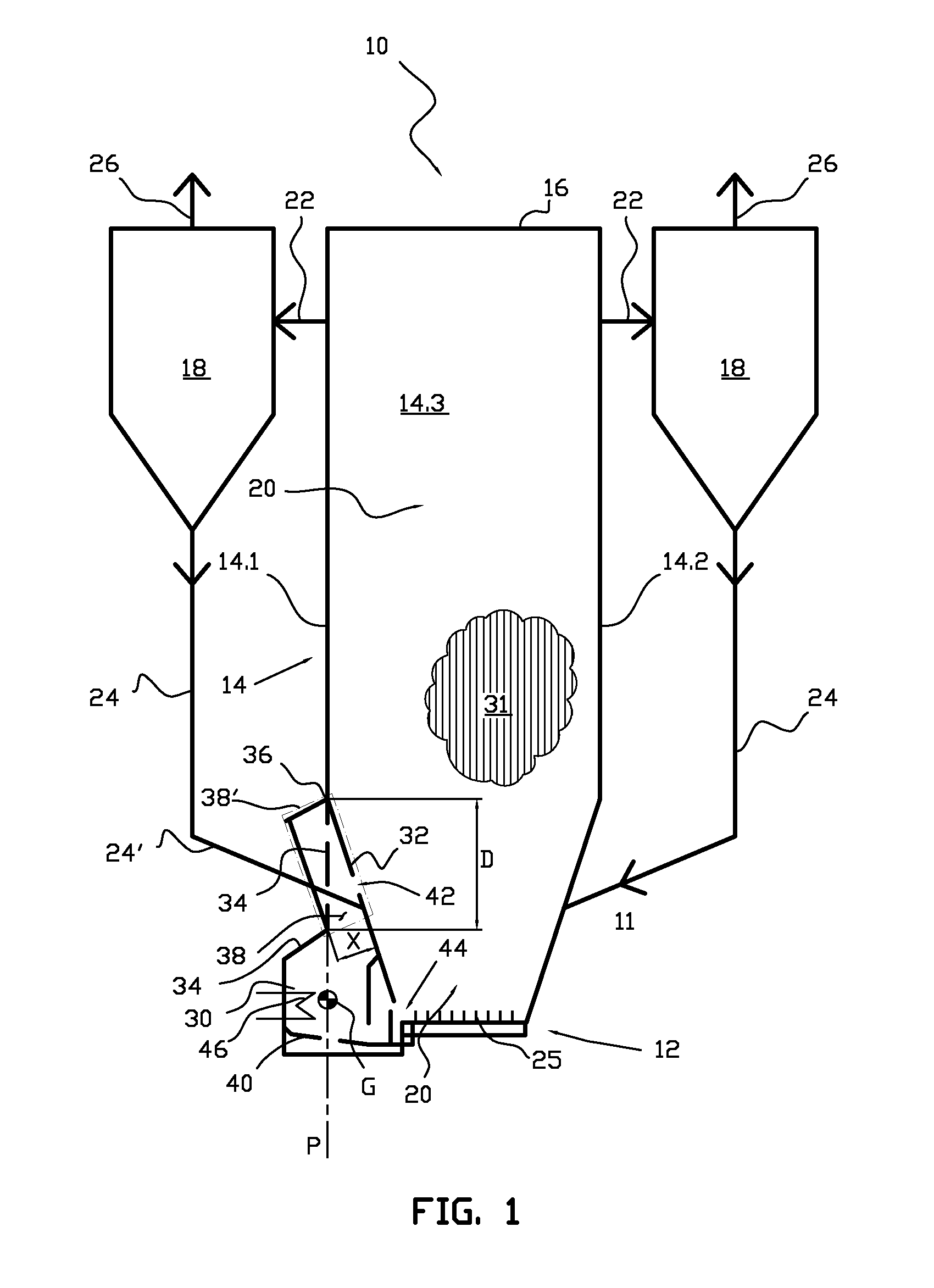
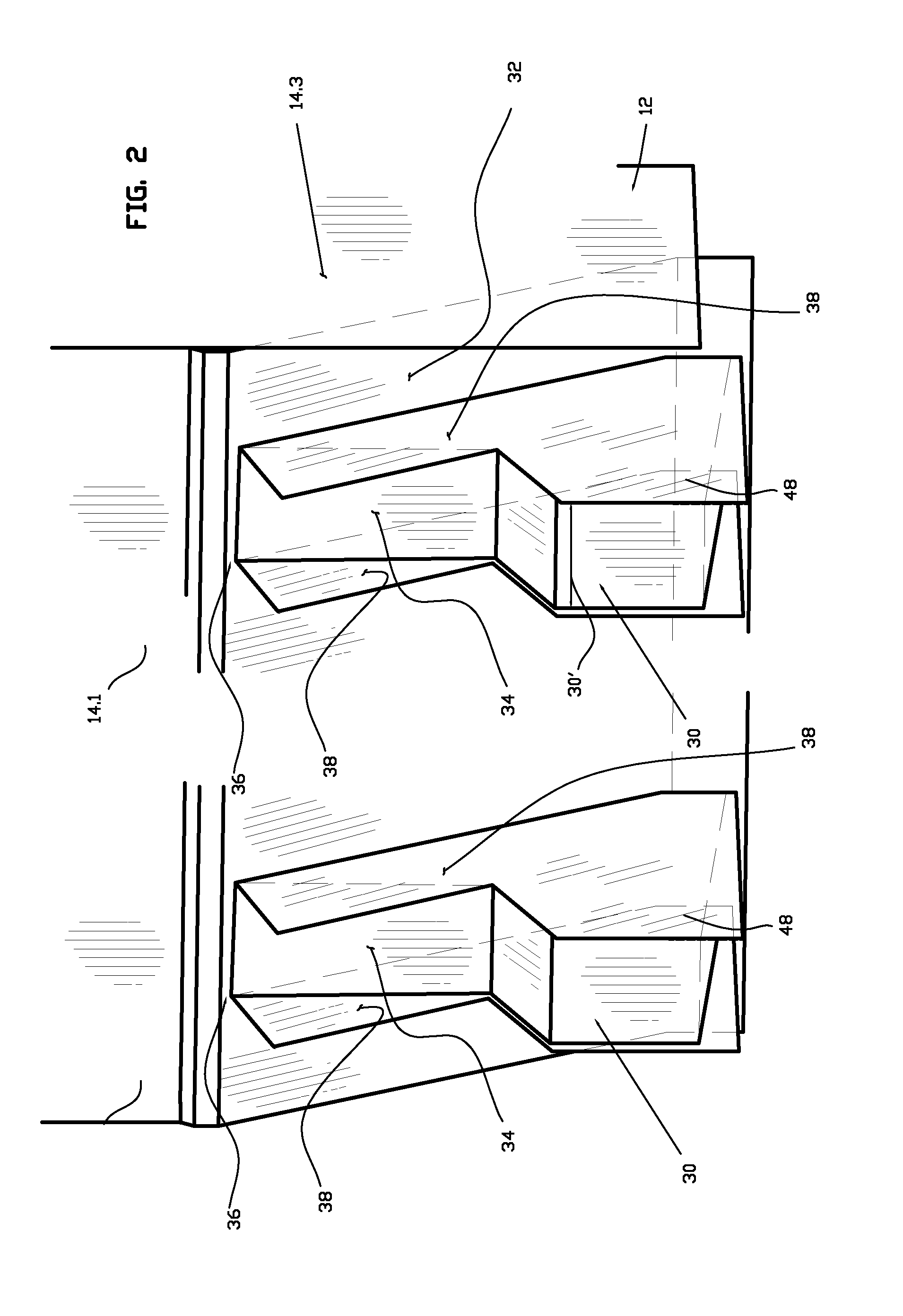
[0028]The invention is described below, when applicable, with reference to both FIG. 1 and FIG. 2, in which the same reference numbers are used when referring to corresponding features. FIG. 1 schematically illustrates an embodiment of the fluidized bed reactor arrangement 10 in accordance with the invention. The fluidized bed reactor arrangement 10 comprises a fluidized bed reactor, having, for example, a reactor chamber 20, and a solids separator 18. The fluidized bed reactor is preferably a circulating fluidized bed boiler. FIG. 2 illustrates a heat exchange chamber 30 of a fluidized bed reactor arrangement in the lower portion of the reactor.

[0029]A circulating fluidized bed boiler 10 comprises a bottom portion 12, a roof portion 16, and walls 14 extending therebetween. Further, it is clear that the fluidized bed reactor comprises many parts and elements that are not shown here, for the sake of clarity. The bottom portion, the roof portion and the walls 14 form the reaction cham...


PUM


Abstract

A fluidized bed reactor arrangement includes a bottom portion and a roof portion. A reaction chamber is defined by at least one side wall extending between the bottom portion and the roof portion. The at least one side wall includes a vertically extending portion having a lower end and a lower portion, which lower portion is inclined in such a manner that a cross section of the reaction chamber decreases towards the bottom portion. A heat exchange chamber, outside of the reaction chamber, is at the lower portion of the at least one side wall. The lower portion of the at least one side wall forms a partition wall between the heat exchange chamber and the reaction chamber. The heat exchange chamber extends from the partition wall to a rear wall of the heat exchange chamber.

Description

[0001]This application is a U.S. national stage application of PCT International Application No. PCT / FI2011 / 050150, filed Feb. 18, 2011, published as International Publication No. WO 2011 / 104434 A1, and which claims priority from Finnish patent application number 20105190, filed Feb. 26, 2010.FIELD OF THE INVENTION[0002]The present invention relates to a fluidized bed reactor arrangement in which a fluidized bed reactor comprises at least a bottom portion, a roof portion and at least one side wall vertically extending between the bottom portion and the roof portion, the side wall being arranged to be inclined at the lower portion thereof in such a manner that the cross section of the reaction chamber of the reactor decreases towards the bottom portion, and which fluidized bed reactor arrangement comprises a heat exchange chamber at the inclined area of the side wall outside of the reaction chamber, and which side wall, extending between the bottom portion and the roof portion and be...

Claims


Application Information

Patent Timeline
Patent Type & Authority Patents(United States)
IPC IPC(8): B01J8/18F27B15/02F01K23/06F22B29/06F22B31/00F22G1/02F23C10/10F27D17/00B01J8/08B01J8/24B01J19/00B01J19/24F28C3/00F28C3/10F28C3/12F28C3/16F27B15/00F27D99/00F28D13/00B01J8/00
CPCF27B15/02F01K23/061F22B29/06F22B31/0007F22G1/02F23C10/10F27D17/004F22B31/0092F23C10/04F22B31/00F27B15/16
Inventor LANKINEN, PENTTI
Owner AMEC FOSTER WHEELER ENERGIA
Learn More