
Oscillator for timepiece movement

Active Publication Date: 2018-01-04
JEANNERET MARC ANDRE
View PDF8 Cites 0 Cited by
  • Summary
  • Abstract
  • Description
  • Claims
  • Application Information

AI Technical Summary

Benefits of technology

The present invention proposes an oscillator for clocks that does not require a balance-spring and offers good chronometric results with a simple and robust structure that is not very sensitive to external changes. Additionally, it can be easily integrated into existing clockwork calibers without requiring significant modifications. The oscillator uses the repulsion between magnets to generate a return force, and the stationary magnet directly performs the mechanical banking function, eliminating any risk of seizing of the balance in case of impact. The balance also has a pin that cooperates with the pallet to sustain the oscillations. Overall, the invention offers improved performance and reliability without complicating the assembly process.

Problems solved by technology

Yet the manufacture of oscillators of the sprung balance type is delicate to master; in particular, producing the balance-springs requires very precise know-how that is not very widespread, which justifies the search for alternative solutions.
Such a construction is supposed to lead to high-frequency oscillations of the pallet, for which it is probably difficult to ensure a good level of isochronism.

Method used


Image

  • Oscillator for timepiece movement
  • Oscillator for timepiece movement
  • Oscillator for timepiece movement

Examples


Embodiment Construction

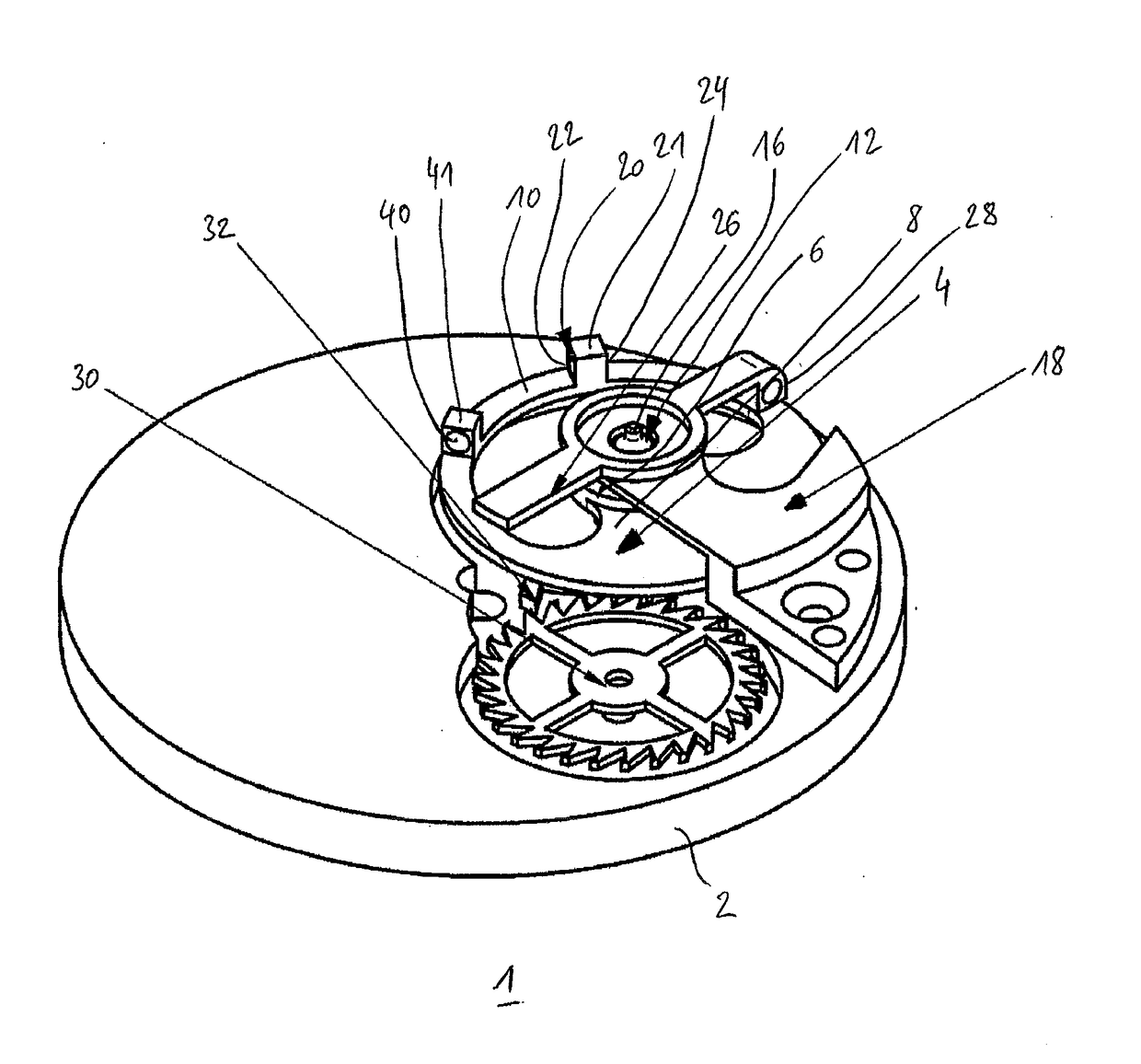
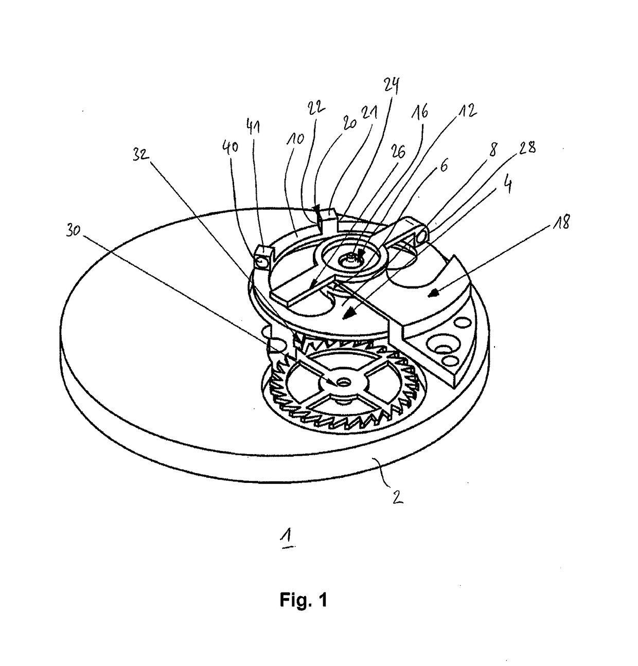
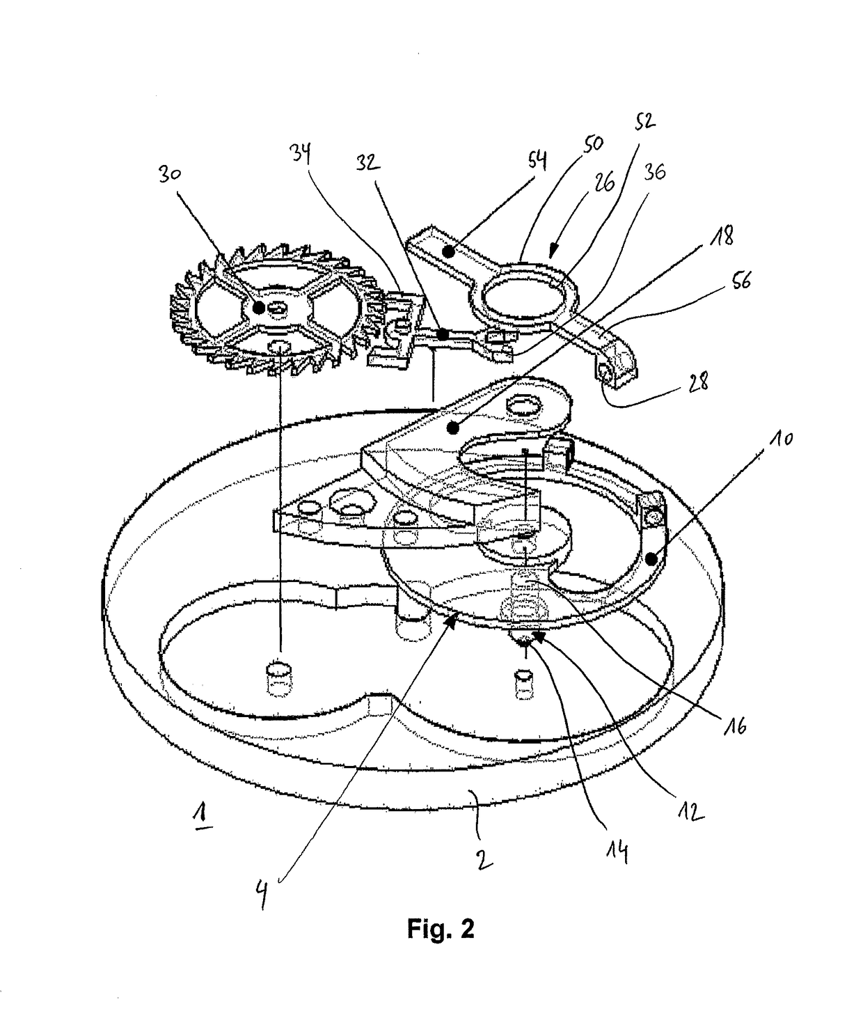
[0019]FIG. 1 shows a simplified perspective view of a clockwork movement including an oscillator 1 according to one preferred embodiment of the present invention, while FIG. 2 shows the clockwork movement of FIG. 1 in a similar, but exploded view, to show certain construction details.

[0020]The depiction of the clockwork movement is simplified in the figures to facilitate the comprehension of the features of the oscillator according to the invention.

[0021]The clockwork movement can be an existing caliber slightly modified to install the oscillator according to the invention therein, or alternatively, it may be a new caliber developed specifically, without going beyond the scope of the invention.

[0022]The clockwork movement includes a frame, in particular here a plate 2 machined conventionally to support all or part of the wheels of the movement. In particular, the plate typically supports an energy source, such as a spring housed in a barrel (not illustrated), intended to sustain the...


PUM


Abstract

The invention concerns an oscillator for a timepiece movement, comprising a staff rigidly connected to a balance carrying first and second bipolar magnets spaced apart from the staff and capable, depending on the angular position of the balance, of being positioned alternately within range of a magnetic field produced by a fixed bipolar magnet, the latter being located on the trajectory of the first and second bipolar magnets and being arranged in such a way that, when one of the bipolar magnets approaches the fixed bipolar magnet, identical polarities are located opposite each other in order to produce a repulsive force. The oscillator further comprises a pallet assembly and an escape wheel for establishing a kinematic connection between a source of energy of the timepiece movement and the balance staff, and arranged in such a way that the balance is capable of having a sustained periodic oscillating movement of an amplitude greater than 90 degrees.

Description

TECHNICAL FIELD[0001]The present invention relates to an oscillator for a timepiece movement, including an arbor intended to be mounted on a frame element of the clockwork movement to define the rotation axis of a balance comprising a hub secured to a suspended mass, angularly extended, bearing a first bipolar magnet, arranged at a distance from the arbor, the magnetic poles of which are oriented substantially in a tangential direction in reference to the arbor, and able, depending on the angular position of the balance, to be positioned within range of a magnetic field produced by at least one stationary bipolar magnet, secured to a support intended to be assembled to the frame of the clockwork movement, the stationary bipolar magnet being situated on the trajectory of the first bipolar magnet as defined by the rotation of the balance, while being arranged on the support such that, when the first bipolar magnet comes closer to the stationary bipolar magnet, identical polarities are...

Claims


Application Information

Patent Timeline
IPC IPC(8): G04C3/04G04B17/32G04C5/00G04B17/22
CPCG04C3/047G04C5/005G04B17/32G04B17/22G04B17/063G04B17/222G04B15/00
Inventor JEANNERET, MARC ANDRESTIFANI, SALVATORE STEFANO
Owner JEANNERET MARC ANDRE
Learn More