Illuminated optical enlargement device

a technology of illumination and optical enlargement, which is applied in the field of illumination optical enlargement devices, can solve the problems of frequent replacement of batteries and considerable drawbacks

Inactive Publication Date: 2002-05-07
LIFATEC GMBH FASEROPTIK & OPTOELEKTRONIK
View PDF12 Cites 35 Cited by
  • Summary
  • Abstract
  • Description
  • Claims
  • Application Information

AI Technical Summary

Problems solved by technology

A disadvantage for the abovementioned device presents itself in that, due to the relatively high-energy consumption of the incandescent bulbs, the batteries must be changed frequently.
Furthermore, one must provide for the possibility of changing the incandescent bulbs since these come with only a limited lifetime.
In addition, a considerable drawback is incurred with the device mentioned in directing the light emitted by the incandescent bulbs to the object to be observed by means of reflection from the concave surface of the plano-concave lens.

Method used


Image

  • Illuminated optical enlargement device
  • Illuminated optical enlargement device
  • Illuminated optical enlargement device

Examples


Embodiment Construction

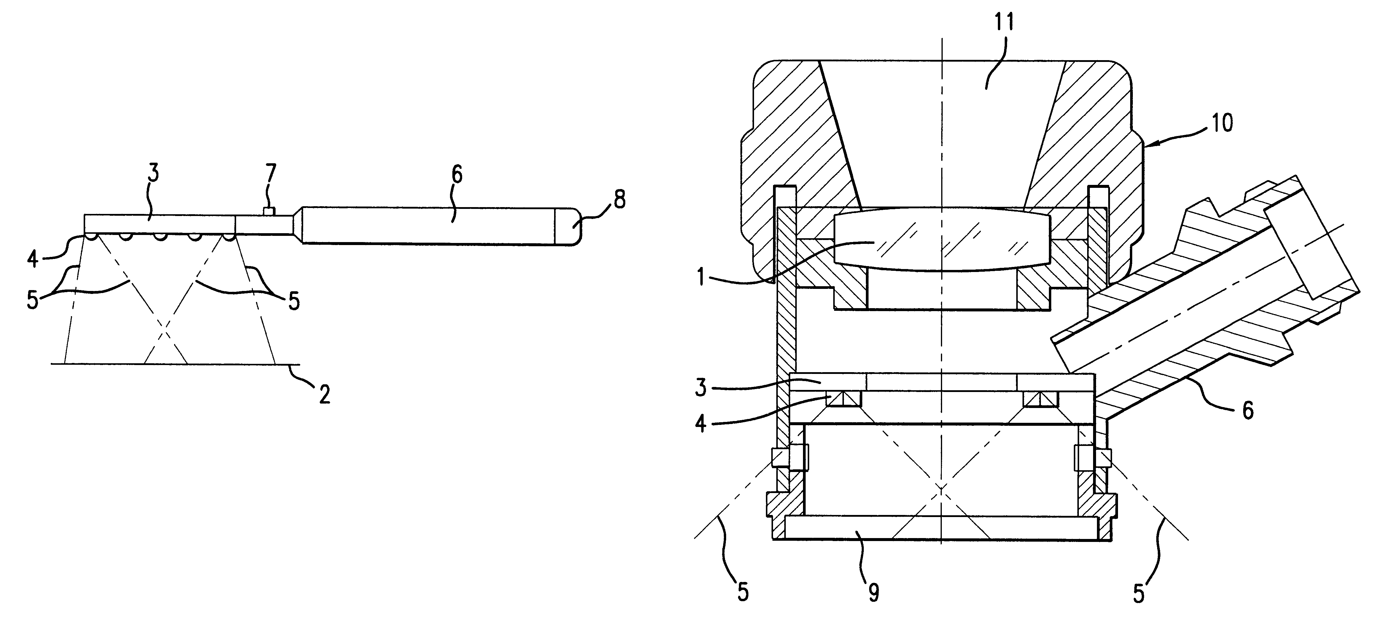
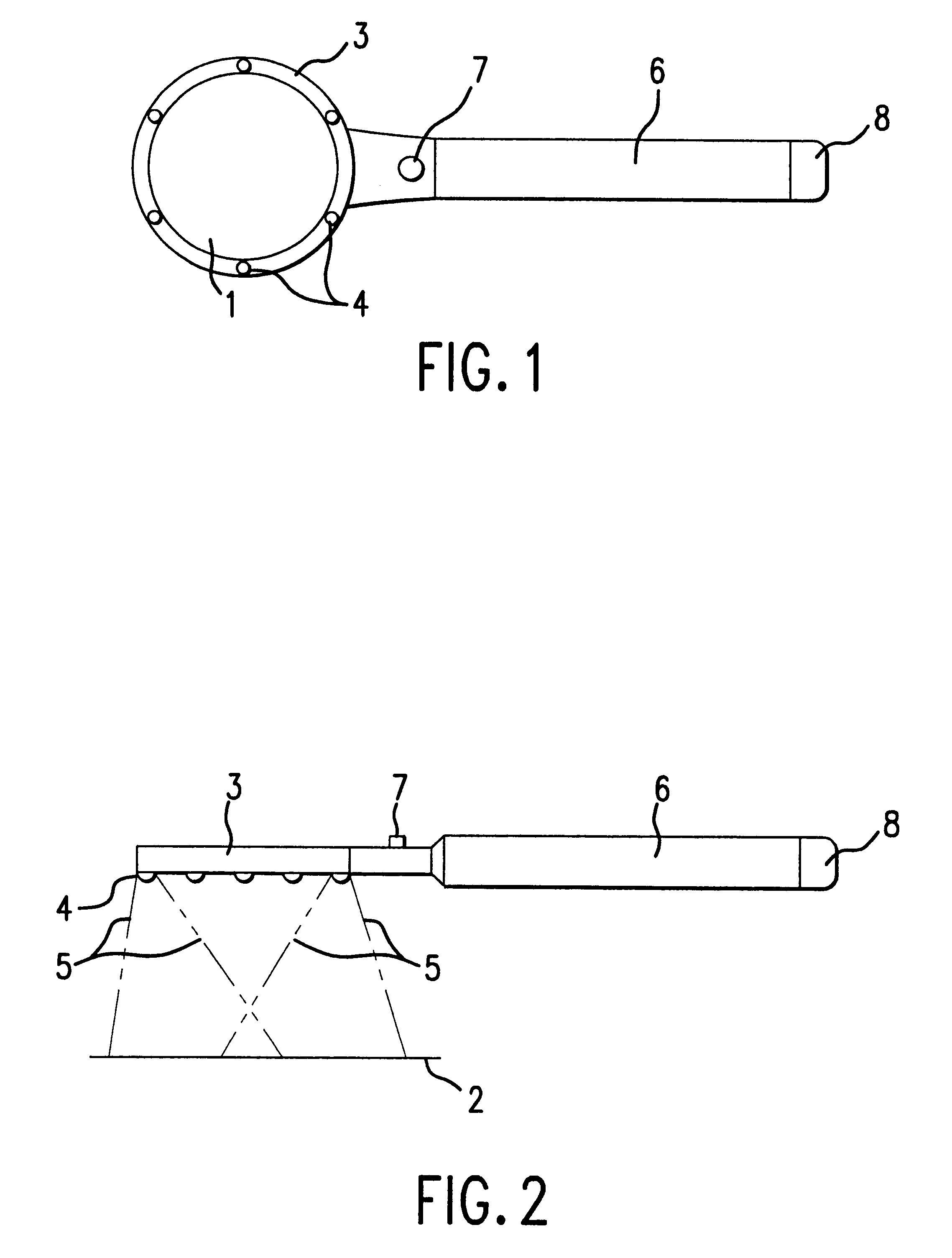
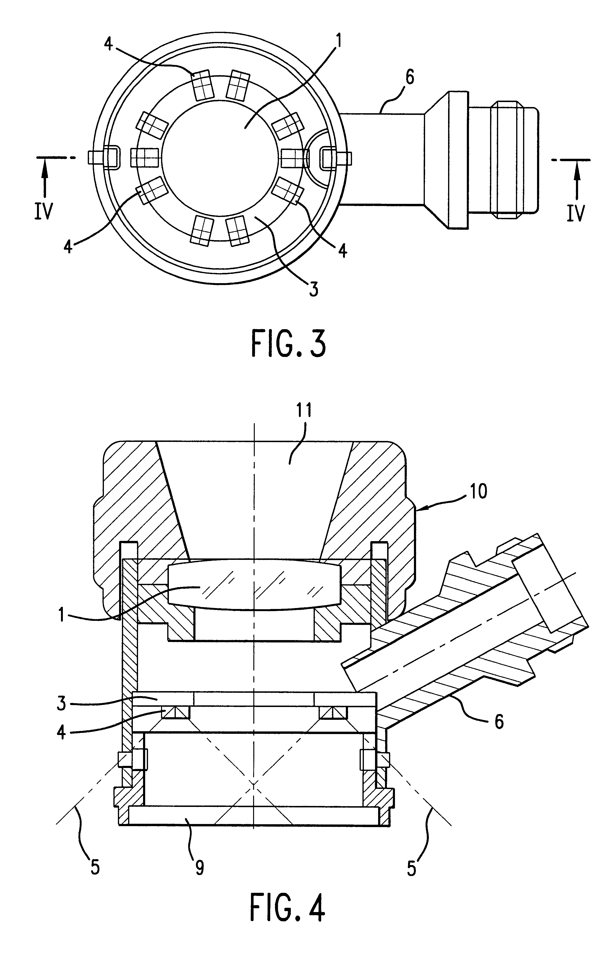
As illustrated in FIG. 1, the illuminated optical magnifying device shown in the includes an optical focusing unit 1, which in the design example shown has a circular contour or ring-shaped cross-section. This optical focusing unit 1 can, for example, comprise of at least one convex lens or also of achromatic lenses or a combination of convex lenses and achromatic lenses or something similar. According to the invention, the optical focusing unit 1 can be so configured that lens errors such as spherical aberration, astigmatism, field curvature, distortion and chromatic aberration can be largely eliminated. The additional possibility exists of providing at least one of the optically functional surfaces used for focusing with a reflection-reducing coating. In particular, a multiple coating can be applied so that reflections in the visible spectral range could be reduced to less than 1%, in some cases less than 0.5%.

As shown in FIG. 2, the magnifying device, as with using a magnifying g...


PUM


Abstract

An illuminated optical magnifying device with an optical focusing unit that can produce a magnified image of an object to be observed and with an illumination device whose light is at least partially applicable for illuminating the object to be observed, whereby the illumination device is composed of at least one luminous diode, which is arranged in the magnifying device in such a way that its light can emerge from the magnifying device essentially straight toward the direction of the object to be observed.

Description

The present application claims priority to German Patent Application No. 199 50 899.2 filed Oct. 22, 1999 the entirety of which is herein incorporated by reference.1. Field Of The InventionThe present invention concerns an illuminated optical magnifying device, in particular a magnifying device with an optical focusing unit that can produce a magnified image of an object to be viewed and with an illumination device whose light can at least partially be used to illuminate the object to be lit.2. The Prior ArtA magnifying device of the type described above is recognized from the German Patent Specification DE 39 15 119 C1. For the magnifying device described therein, which is primarily applicable as a reading lens, the focusing unit consists of a plano-convex lens and a plano-concave lens whose concave surface faces the plane surface of the plano-convex lens so that, except for the outer ring-shaped edge of the plane surface of the plano-convex lens, there is an air gap between the tw...

Claims


Application Information

Patent Timeline
Patent Type & Authority Patents(United States)
IPC IPC(8): G02B25/02G02B25/00
CPCG02B25/02
Inventor MULLER, PETERGLAUM, HORSTHEMPFLING, RUDIGER
Owner LIFATEC GMBH FASEROPTIK & OPTOELEKTRONIK
Why Eureka
Try Eureka