Network camera system and network camera thereof

a network camera and camera system technology, applied in the field of network camera systems and network cameras thereof, can solve the problems of time-consuming and laborious related installation process, complex wiring design of network camera systems, and many inconveniences in setting up network cameras

Inactive Publication Date: 2016-03-24
VIVOTEK INC
View PDF8 Cites 11 Cited by
  • Summary
  • Abstract
  • Description
  • Claims
  • Application Information

AI Technical Summary

Benefits of technology

[0006]However, if the installer wants to set up an additional network camera, the installer also needs to set up an additional power-over-Ethernet switch to be connected to the additional network camera and the pervious power-over-Ethernet switch for establishing network signal transmission, and the additional power-over-Ethernet switch also needs to be connected to the external power source for providing a network power to the additional network camera, so as to make the related installation process time-consuming and strenuous. Furthermore, if there is no external power source around the position where the network camera is set up, the installer needs to set up an external power source in advance. Accordingly, it may not only cause much inconvenience in setting up the network camera, but also cause the aesthetic problem due to complicated wiring of the external power source and the power-over-Ethernet switch. Moreover, since the installer needs to have a corresponding construction license for wiring the external power source in some countries, it could further increase the construction cost and time for setting up the network camera, so as to limit the practical application of the network camera.

Problems solved by technology

However, if an installer wants to set up a network camera system with many network cameras, the wiring design of the network camera system can be very complicated since each network camera needs to be connected to the external power source and the control terminal.
However, if the installer wants to set up an additional network camera, the installer also needs to set up an additional power-over-Ethernet switch to be connected to the additional network camera and the pervious power-over-Ethernet switch for establishing network signal transmission, and the additional power-over-Ethernet switch also needs to be connected to the external power source for providing a network power to the additional network camera, so as to make the related installation process time-consuming and strenuous.
Accordingly, it may not only cause much inconvenience in setting up the network camera, but also cause the aesthetic problem due to complicated wiring of the external power source and the power-over-Ethernet switch.
Moreover, since the installer needs to have a corresponding construction license for wiring the external power source in some countries, it could further increase the construction cost and time for setting up the network camera, so as to limit the practical application of the network camera.

Method used


Image

  • Network camera system and network camera thereof
  • Network camera system and network camera thereof
  • Network camera system and network camera thereof

Examples


Embodiment Construction

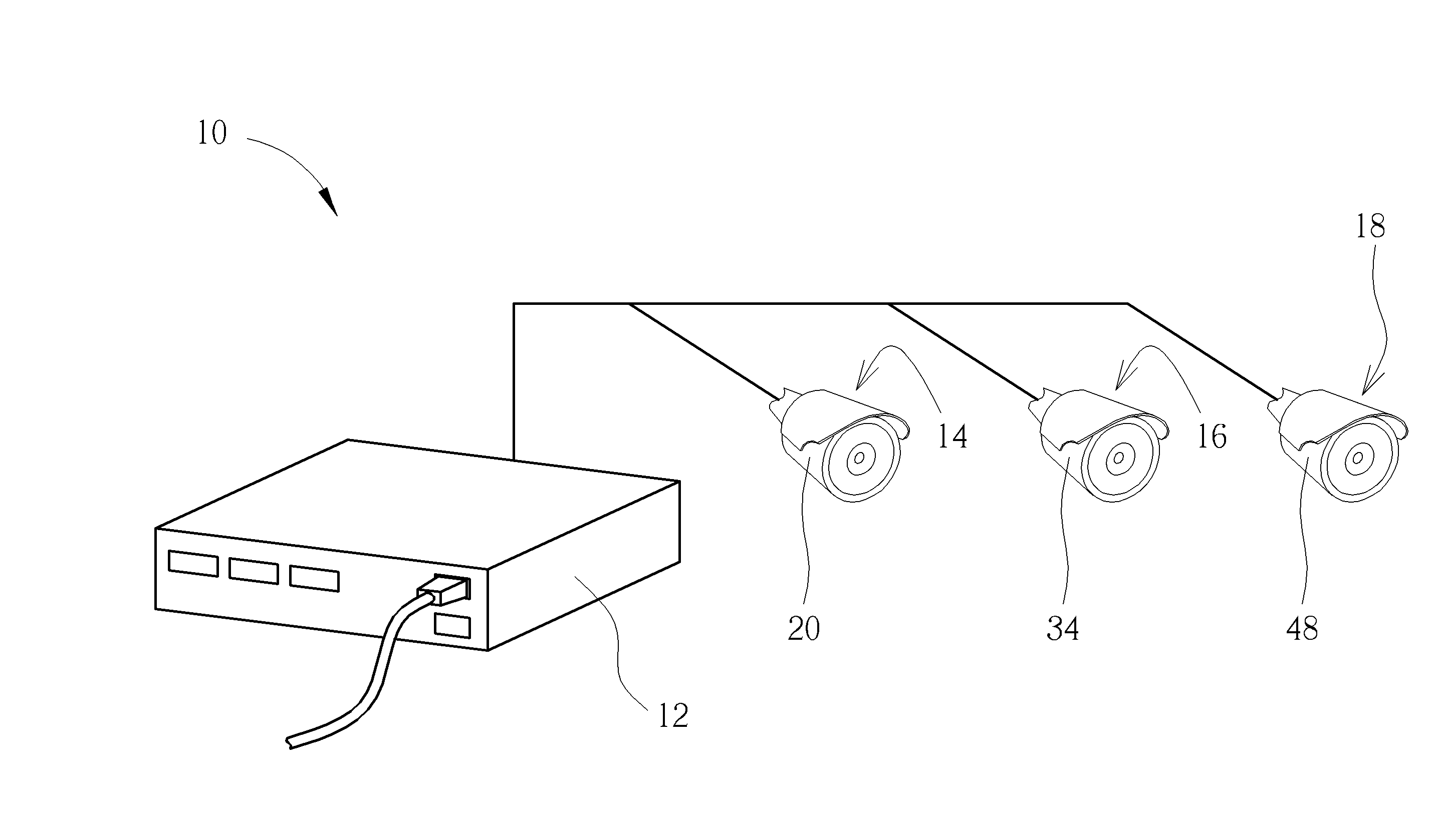
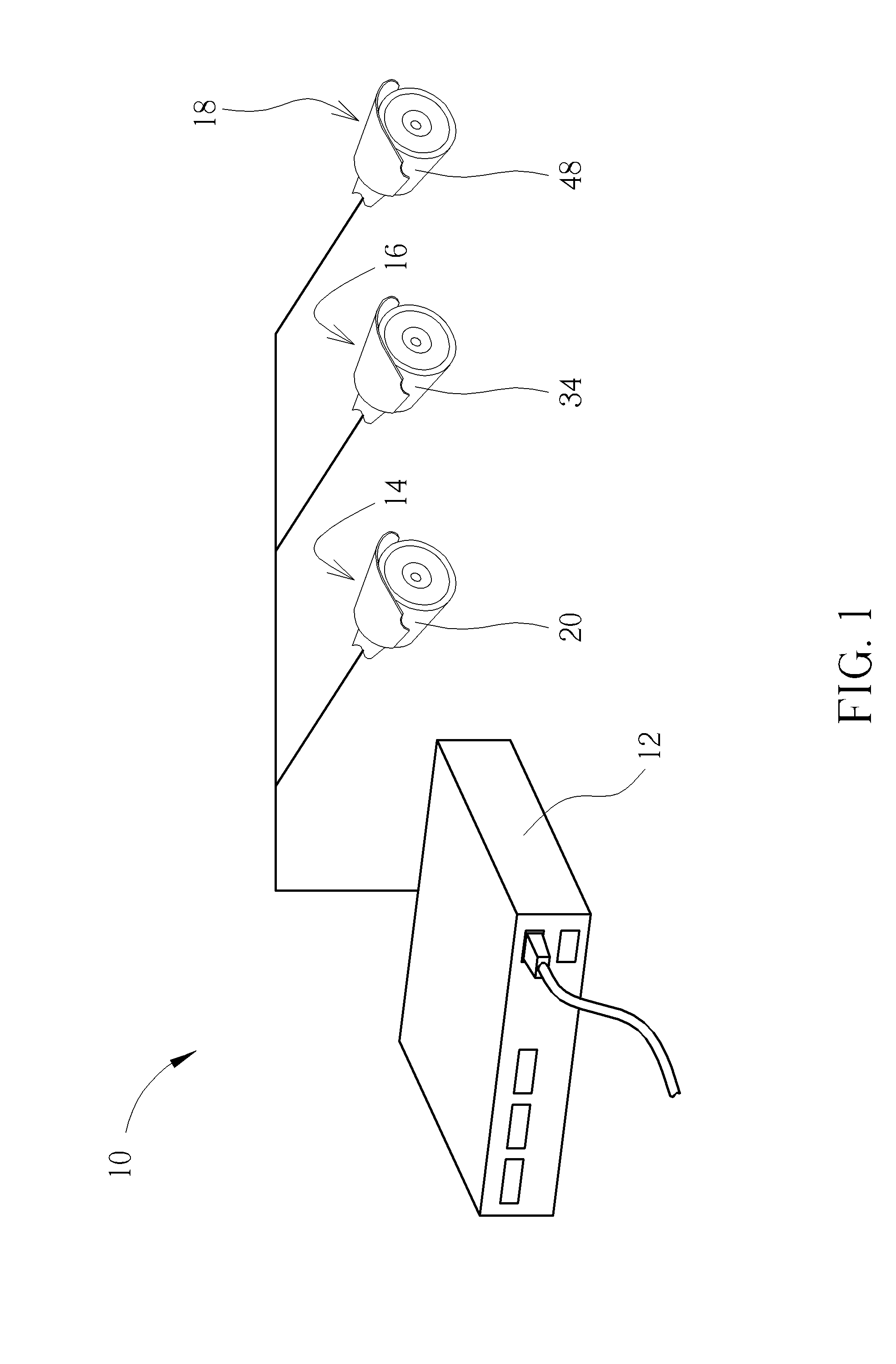
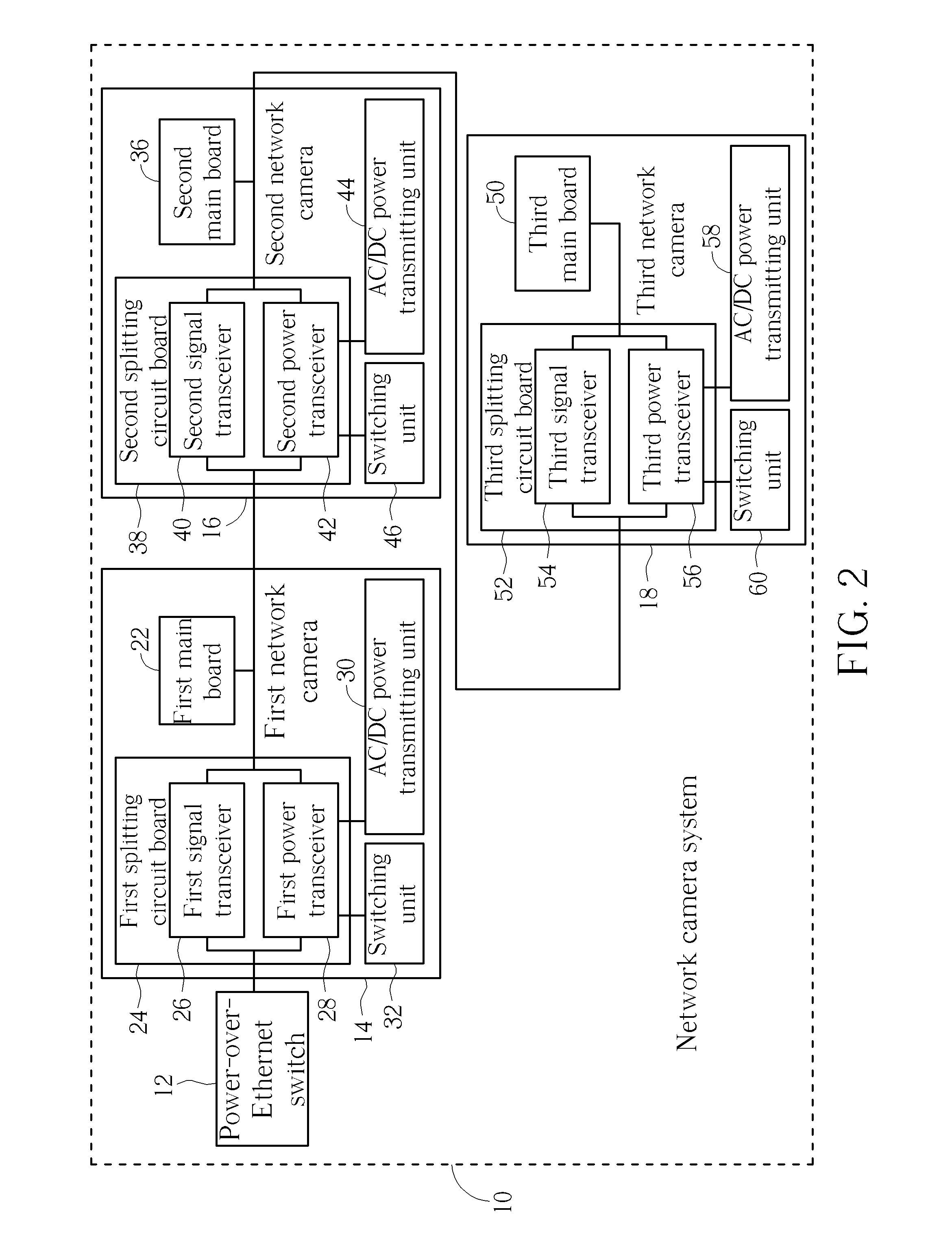
[0012]Please refer to FIG. 1 and FIG. 2. FIG. 1 is diagram of a network camera system 10 according to an embodiment of the present invention. FIG. 2 is a functional diagram of the network camera system 10 in FIG. 1. As shown in FIG. 1 and FIG. 2, the network camera system 10 includes a power-over-Ethernet switch 12, at least one first network camera 14, at least one second network camera 16, and at least one third network camera 18. Amount of the first network camera 14, the second network camera 16, and the third network camera 18 is not limited to one as shown in FIG. 1, but could vary with the practical application of the network camera system 10. The power-over-Ethernet switch 12 is connected to the first network camera 14 and a control terminal (e.g. an image control host) in a network cable connecting manner for providing a network power to the first network camera 14 and establishing network signal transmission between the first network camera 14 and the control terminal, so ...


PUM


Abstract

A network camera system includes a network camera and a power-over-Ethernet switch for providing a network power. The network camera is connected to the power-over-Ethernet switch via a network cable and includes a casing, a main board, and a splitting circuit board. The main board is disposed in the casing for operating the network camera. The splitting circuit board is disposed in the casing and connected to the main board and the power-over-Ethernet switch. The splitting circuit board includes a signal transceiver and a power transceiver. The signal transceiver is used for performing network signal transmission between the power-over-Ethernet switch and the main board. The power transceiver is used for selectively splitting a first splitting power from the network power to the main board as an operating power of the network camera.

Description

BACKGROUND OF THE INVENTION[0001]1. Field of the Invention[0002]The present invention relates to a network camera system and a network camera thereof, and more specifically, to a network camera system utilizing a splitting circuit board disposed in a network camera to split network power and a network camera thereof.[0003]2. Description of the Prior Art[0004]In general, a conventional network camera is usually connected to an external power source via a power cord for obtaining an operating power, and is connected to a control terminal (e.g. an image control host) via a network cable for establish signal transmission between the control terminal and the network camera. However, if an installer wants to set up a network camera system with many network cameras, the wiring design of the network camera system can be very complicated since each network camera needs to be connected to the external power source and the control terminal.[0005]With development of power-over-Ethernet technolo...

Claims


Application Information

Patent Timeline
Patent Type & Authority Applications(United States)
IPC IPC(8): H04N5/232H04N5/225
CPCH04N5/2252H04N5/23206H04L12/10H04N23/661H04N23/51
Inventor CHEN, MING-TSUNG
Owner VIVOTEK INC
Why Eureka
Try Eureka