

Cutting Blade
- Summary
- Abstract
- Description
- Claims
- Application Information
AI Technical Summary
Benefits of technology
Problems solved by technology
Method used
Image

Examples
Embodiment Construction
[0110]The blade herein can be used for example in the straw chopper construction of the general type shown in the prior patents of Redekop Manufacturing which are U.S. Pat. Nos. 6,840,854; 5,232,405 and 5,482,508, the disclosures of which are incorporated herein by reference.
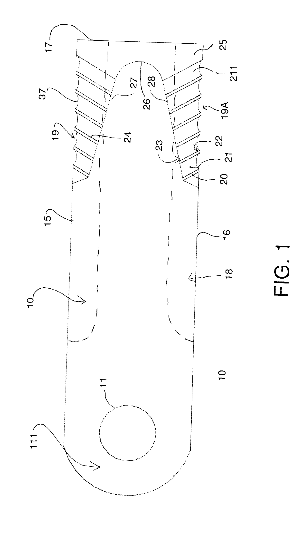
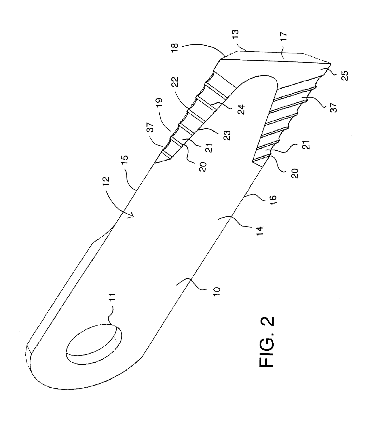
[0111]The blades includes a plate 10 having a mounting hole 11 through the plate for mounting on a bushing carried on a pin of a rotor (not shown). While one mounting hole is shown allowing the blade to act as a flail pivotal around the axis of the mounting hole, other mounting arrangements can be provided.
[0112]The blade 10 comprises a generally flat elongate blade of a base material 12 having a top surface 13, a bottom surface 14, two side edges 15, 16 and an end edge 17. The blade is typically stamped from uncoiled strip steel rolls but other manufacturing arrangements can be used.
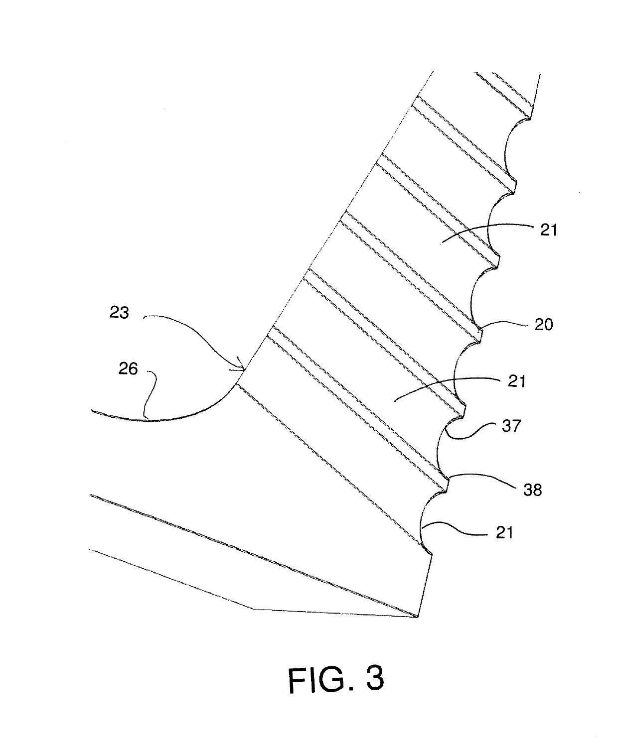
[0113]At least one side edge 15 or 16, and typically both side edges, is chamfered at edge 18 to form a cutting edge 19, 19A on th...
PUM
 Abstract
Description
Claims
Application Information