Apparatus and method for fillet punch creep testing

a creep test and apparatus technology, applied in the field of creep testing, can solve the problems of reducing the level, unable to predict the remaining life of in-service parts of the system, and the methods that reveal problems and limitations, so as to reduce the number of tests required, and eliminate the concentration of stress in the specimen.

Active Publication Date: 2019-05-09
MORADI ALI
View PDF2 Cites 2 Cited by
  • Summary
  • Abstract
  • Description
  • Claims
  • Application Information

AI Technical Summary

Benefits of technology

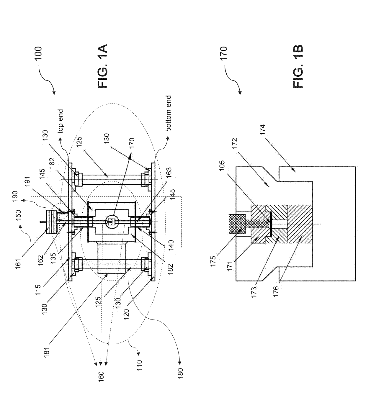
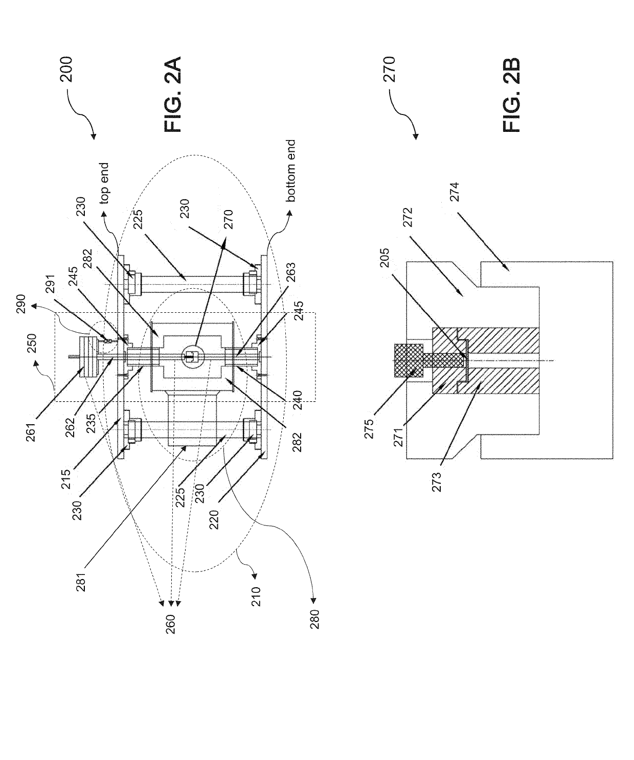
[0009]In a further aspect, filleted edges in the filleted lower die and the filleted punch can eliminate stress concentration in the specimen resulting in stable measurements, and thus, reducing the number of tests required for reliable results. The specimen can also include a small amount with no constraint in thickness and no need for special specimen preparation, which can result in a non-destructive and less time-consuming process to produce different stages of the creep curve during creep testing. The loading weight can also apply a constant load from the loading rod to the filleted punch, and subsequently to the specimen, which in turn can prevent dispersion in the measured data, and can make the fillet punch creep testing to be done repeatedly in order to predict a remaining life of in-service parts of a system.

Problems solved by technology

The most commonly used standard testing method is a conventional Uniaxial Creep Test, which not only requires a large amount of sample material, but also involves a destructive and time-consuming process; thus, it cannot be used to predict the remaining life of in-service parts of a system.
Despite their powerful tools for evaluating creep characteristics of materials, these methods reveal some problems and limitations.
For example, based on the spherical or pyramidal shape of the indenter in the Indentation Creep Test, the contact area with the specimen increases over time, and thus, the stress level decreases, which makes it difficult to control such contact stress, and leads to higher stress concentration.
Even though the cylindrical indenter shape in the Compression Creep Test resolves such issue, both indentation methods still rely on compressive forces for testing, which ultimately cannot provide a third stage of a creep curve for analysis.
Similarly, the sharp edges in the cylindrical punch and in the die of the Shear Punch Creep Test result in high stress concentration on the contact area and high dispersion in the measured data making it questionable to repeat the creep testing to produce a reliable creep curve.
Nonetheless, a first stage of the creep curve cannot also be determined using the Shear Punch Creep Test.
Likewise, while the spherical shape punch in the Small Punch Creep Test reduces the amount of dispersion in the measured data, local failures can still occur.
Also, the contact area of the punch in the Small Punch Creep Test increases over time, as does the amount of applied stress on the specimen, which ultimately leads to difficulty in controlling the applied stress.
As such, this data transformation can always encounter difficulty when using these miniaturized testing techniques.
Therefore, the entire process can lead to increase in testing time and labor intensity, and thus cost inefficiency.

Method used


Image

  • Apparatus and method for fillet punch creep testing
  • Apparatus and method for fillet punch creep testing
  • Apparatus and method for fillet punch creep testing

Examples


Embodiment Construction

[0045]In the following detailed description, numerous specific details are set forth by way of examples in order to provide a thorough understanding of the relevant teachings. However, it should be apparent to those skilled in the art that the present teachings may be practiced without such details. In other instances, well known methods, procedures, components, and / or circuitry have been described at a relatively high-level, without detail, in order to avoid unnecessarily obscuring aspects of the present teachings. As part of the description, some of this disclosure's drawings represent structures and devices in block diagram form in order to avoid obscuring the invention. In the interest of clarity, not all features of an actual implementation are described in this specification. Moreover, the language used in this disclosure has been principally selected for readability and instructional purposes, and may not have been selected to delineate or circumscribe the inventive subject m...


PUM

PropertyMeasurementUnit
radiiaaaaaaaaaa
diameteraaaaaaaaaa
radiusaaaaaaaaaa

Abstract

An improved apparatus and method for fillet punch creep testing of a small specimen comprises, in one implementation, a testing unit secured to a top end and a bottom end of a structural support unit, and configured to conduct creep testing on a specimen. The testing unit includes a loading unit, a fillet punch unit, a thermal unit, and a measuring unit. A filleted punch of the fillet punch unit transfers an applied pressure from the loading unit to the specimen clamped between an upper die and a filleted lower die of the fillet punch unit while the thermal unit surrounds the fillet punch unit, and heats the specimen during testing. The optimized filleted edges on the filleted punch and the filleted lower die eliminate stress concentration against the specimen resulting in stable measurements, and thus, reduce the dispersion of applied load during creep testing. Finally, an application of a constant load on the filleted punch prevents dispersion in the measured data being analyzed by the measuring unit, and allows creep testing to be repeated to predict a remaining life of in-service parts of a system.

Description

TECHNICAL FIELD[0001]The present disclosure relates generally to creep testing and, more particularly, to evaluating creep properties of small specimen by using miniaturized fillet punch creep testing.BACKGROUND[0002]Creep testing provides a powerful tool when evaluating a remaining life of in-service components of a system used in different industries, such as oil and gas, and power plants. Conventional creep testing machines are focused on predicting creep properties of a sample material based on standard tests. The most commonly used standard testing method is a conventional Uniaxial Creep Test, which not only requires a large amount of sample material, but also involves a destructive and time-consuming process; thus, it cannot be used to predict the remaining life of in-service parts of a system. As such, a considerable research and development has been done in recent years to improve current creep testing methods.[0003]Recent development has offered a significant promise to est...

Claims


Application Information

Patent Timeline
Patent Type & Authority Applications(United States)
IPC IPC(8): G01N3/24
CPCG01N3/24G01N2203/0033G01N2203/0071G01N3/28
Inventor MORADI, ALI
Owner MORADI ALI
Why Eureka
Try Eureka