A wind turbine blade comprising an aerodynamic blade shell with recess and pre-manufactured spar cap

a technology of aerodynamic blade shell and spar cap, which is applied in the direction of wind turbines with parallel air flow, liquid fuel engine components, wind energy generation, etc., can solve the problems of air pockets, difficult or impossible to remove, and ensure the polymer distribution in the entire mould cavity

Inactive Publication Date: 2015-10-29
LM WP PATENT HLDG
View PDF13 Cites 37 Cited by
  • Summary
  • Abstract
  • Description
  • Claims
  • Application Information

AI Technical Summary

Benefits of technology

[0068]This manufacturing method provides a simple way of forming the aerodynamic shell with a recess at the correct position and for connecting the spar cap at the correct position to the blade shell. Further, the insert ensures that fibre material and sandwich core material does not slide down from the sides of the mould and cause

Problems solved by technology

Ensuring a complete distribution of the polymer in the entire mould cavity is, however, often difficult, and accordingly this often results in so-called dry spots, i.e. areas with fibre material not being sufficiently impregnated with resin.
Thus dry spots are areas where the fibre material is not impregnated, and where there can be air pockets, which are difficult or impossible to remove by controlling the vacuum pressure and a possible overpressure at the inlet side.
This is a time-consuming and tiresome process.
This is not desirable, especially not when the polymer has not hardened, as it can result in deformations in the inserted fibre materia

Method used


Image

  • A wind turbine blade comprising an aerodynamic blade shell with recess and pre-manufactured spar cap
  • A wind turbine blade comprising an aerodynamic blade shell with recess and pre-manufactured spar cap
  • A wind turbine blade comprising an aerodynamic blade shell with recess and pre-manufactured spar cap

Examples


Embodiment Construction

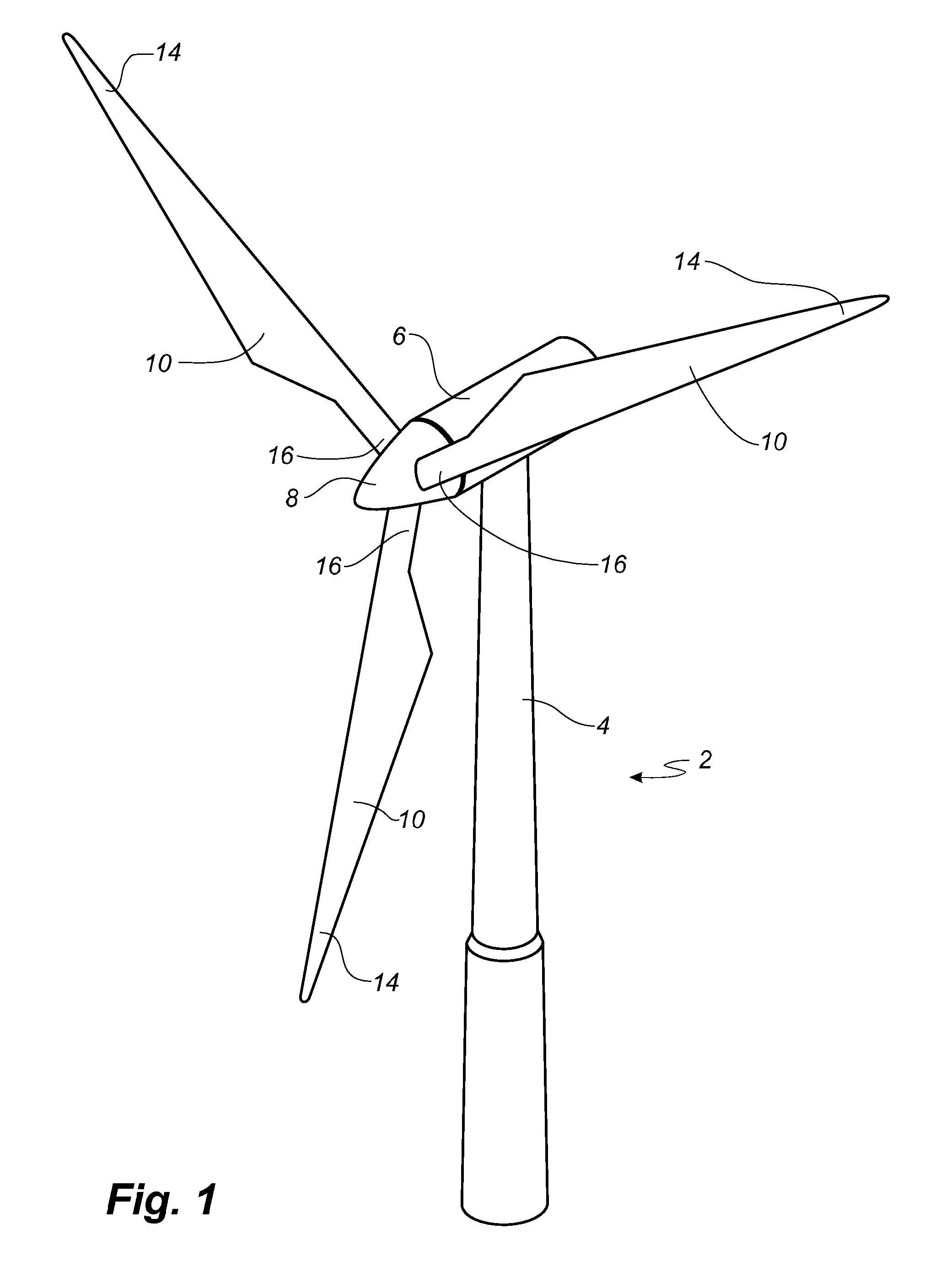
[0097]FIG. 1 illustrates a conventional modern upwind wind turbine according to the so-called “Danish concept” with a tower 4, a nacelle 6 and a rotor with a substantially horizontal rotor shaft. The rotor includes a hub 8 and three blades 10 extending radially from the hub 8, each having a blade root 16 nearest the hub and a blade tip 14 farthest from the hub 8. The rotor has a radius denoted R.

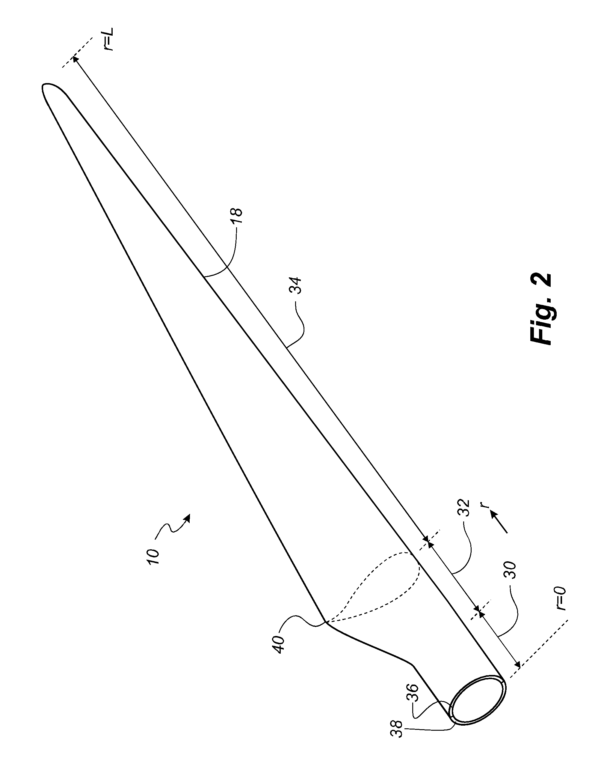
[0098]FIG. 2 shows a schematic view of a first embodiment of a wind turbine blade 10 according to the invention. The wind turbine blade 10 has the shape of a conventional wind turbine blade and comprises a root region 30 closest to the hub, a profiled or an airfoil region 34 farthest away from the hub and a transition region 32 between the root region 30 and the airfoil region 34. The blade 10 comprises a leading edge 18 facing the direction of rotation of the blade 10, when the blade is mounted on the hub, and a trailing edge 20 facing the opposite direction of the leading edge 18.
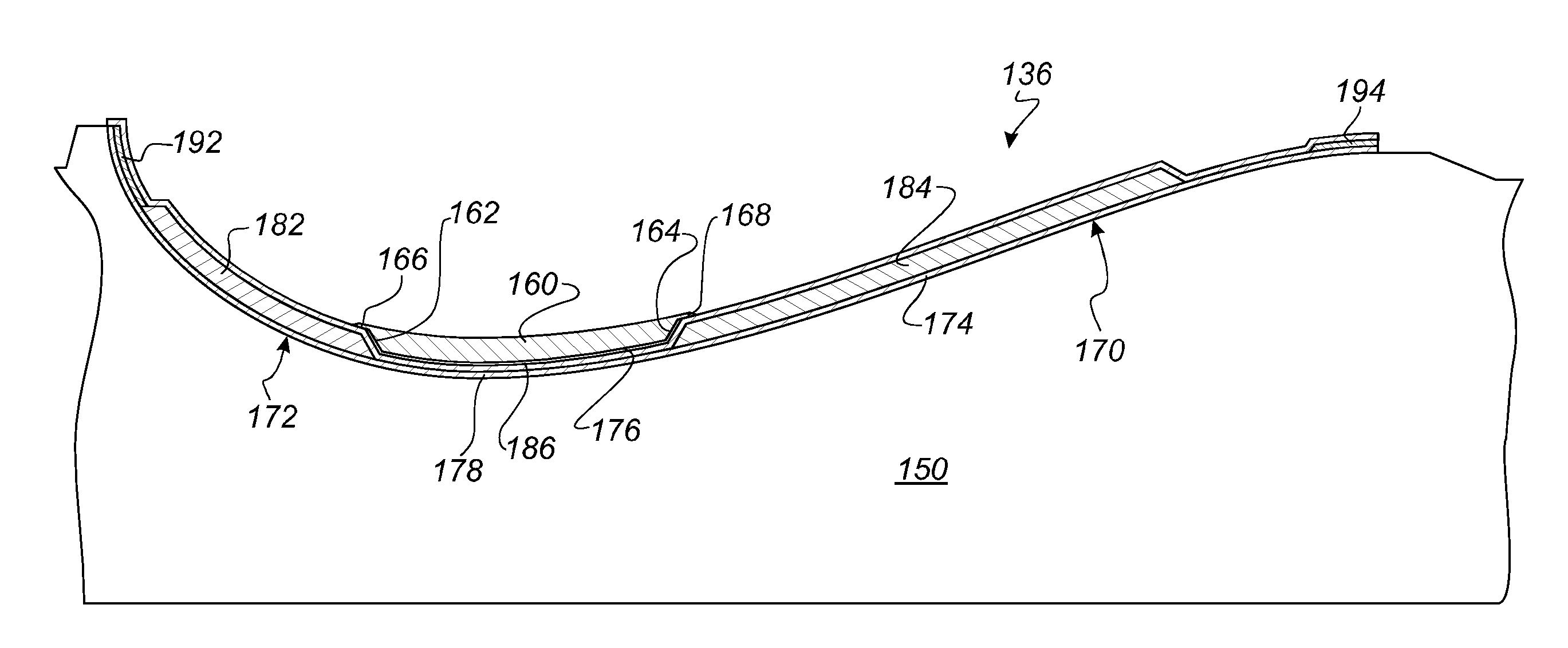
[0099]The...


PUM

PropertyMeasurementUnit
Pressureaaaaaaaaaa
Heataaaaaaaaaa
Aerodynamicaaaaaaaaaa

Abstract

A wind turbine blade has a load carrying structure including at least a first spar cap and an aerodynamic shell having an outer surface forming at least part of an exterior surface of the wind turbine blade and an inner surface. The aerodynamic shell includes a first recess at the inner surface of the blade shell with a first thickened part at a first side of the first recess and a second thickened part at a second side of the first recess. The first recess is tapered towards the first side of the recess and tapered towards the second side of the recess, and the first spar cap is arranged in the first recess of the aerodynamic shell. The first spar cap is tapered towards a first side of the spar cap and further is tapered towards a second side of the spar cap.

Description

TECHNICAL FIELD[0001]The present invention relates to a method of manufacturing a wind turbine blade and intermediate products of a wind turbine blade. The invention further relates to a wind turbine blade and intermediate products of the wind turbine blade.BACKGROUND[0002]Wind turbine blades are often manufactured according to one of two constructional designs, namely a design where a thin aerodynamic shell is glued onto a spar beam, or a design where spar caps, also called main laminates, are integrated into the aerodynamic shell.[0003]In the first design, the spar beam constitutes the load bearing structure of the blade. The spar beam as well as the aerodynamic shell or shell parts are manufactured separately. The aerodynamic shell is often manufactured as two shell parts, typically as a pressure side shell part and a suction side shell part. The two shell parts are glued or otherwise connected to the spar beam and are further glued to each other along a leading edge and trailing...

Claims


Application Information

Patent Timeline
IPC IPC(8): F03D1/06B29C70/48F03D1/00
CPCF03D1/0675F03D1/001B29C70/48B29L2031/085B29K2309/08B29K2067/00B29K2105/08B29C70/443B29C70/543B29C33/306B29C70/541B29D99/0028F03D13/10Y02E10/72Y02P70/50B29C70/342B29C33/60B29K2105/0872B29K2063/00B29K2307/04
Inventor DAHL, MARTINNIELSEN, LARS
Owner LM WP PATENT HLDG
Why Eureka
Try Eureka