Method for measuring and displaying data for chemical reactor tubes

a technology of chemical reactors and tubes, applied in the direction of fluid pressure measurement, fluid tightness measurement, instruments, etc., can solve the problems of high packing density, adversely affecting the efficiency of reaction, and high labor intensity of devices and methods used in the past, so as to improve the ability to measure the back pressure of tubes, less labor intensity, and more accurate

Active Publication Date: 2006-02-23
TUBEMASTER INC
View PDF10 Cites 0 Cited by
  • Summary
  • Abstract
  • Description
  • Claims
  • Application Information

AI Technical Summary

Benefits of technology

[0007] The present invention provides a device and method that improves the ability to measure the back pressure in tubes, making the process much more accurate, faster, less labor intensive, more efficient, safer, less dependent on the skill of the worker, and yielding more accurate and more useful results. In a preferred embodiment, the measuring device uses an inflatable, conforming seal, which provides a good seal between the measuring device and the chemical reactor tubes, even when weldments or other obstructions are present. Also, in a preferred embodiment, the measuring device measures multiple tubes at once rather than measuring only one tube at a time. Also, in a preferred embodiment, measurements are stored at the measuring device, are transmitted electronically to a remote computer, and are displayed graphically in real time at a remote display, such as in the control room, including indications of which tubes are within predetermined specifications and which are not.
[0008] The visual display helps the plant engineer determine which tubes require corrective action and may permit the elimination of the time-consuming prior art process of putting caps on all the tubes as the measurements are being taken.
[0009] Preferred embodiments of the present invention also permit automated handling of the data and prompt statistical analysis and cost-effectiveness analysis of the measurement data in order to help the plant engineer make quick decisions about corrective actions to be taken. The measurements that have been taken with a prototype device made in accordance with the present invention are so accurate that the engineers can begin to recognize what particular variations in pressure drops mean—for example, one pressure drop indicates that a foam pig accidentally has been left in the tube after cleaning, while another indicates that an extra clip has been inserted to retain the catalyst. In addition, in a preferred embodiment of the invention, a device and method are provided to remove dust from the tubes by blowing gas through them.

Problems solved by technology

However, in reality, there is a variation in packings which adversely affects the efficiency of the reaction by providing for different residence times in different tubes.
High back pressures can also indicate problems other than high packing density, such as dust, fines, obstructions in tubes, and the presence of foreign material.
Low back pressures can also indicate problems other than low packing density, such as bridging.
However, the devices and methods that have been used in the past have been labor intensive and time consuming, their accuracy has depended largely upon the skill of the operator, and they have yielded data that is not readily usable.
Weldments and obstructions at the top of the tube can interfere with the ability to obtain a good seal, and failure of the operator to maintain the device in a vertical orientation may also interfere with the ability to obtain a good seal.
Also, the tubes are typically measured one at a time, requiring many workers and a long shut-down time.
With typical prior art methods, it is difficult to keep track of all the measurements, since there may be as many as 35,000 tubes to be measured in a reactor, and transferring data from the many notepads is slow and provides an opportunity for errors.
In order to display the progress of the measurement process, the operators usually put colored caps on the tubes as they are measured, which is time-consuming.

Method used


Image

  • Method for measuring and displaying data for chemical reactor tubes
  • Method for measuring and displaying data for chemical reactor tubes
  • Method for measuring and displaying data for chemical reactor tubes

Examples


Embodiment Construction

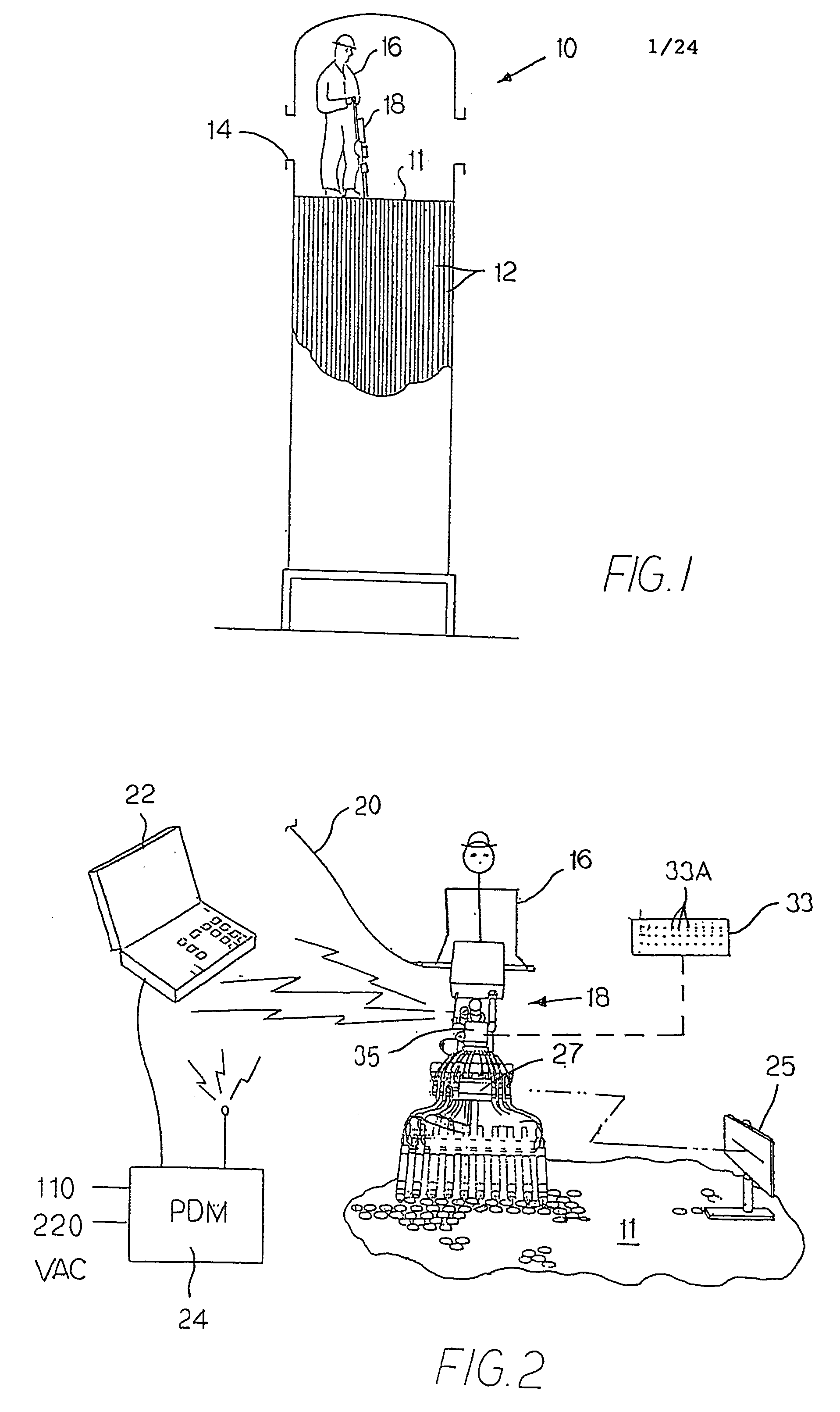
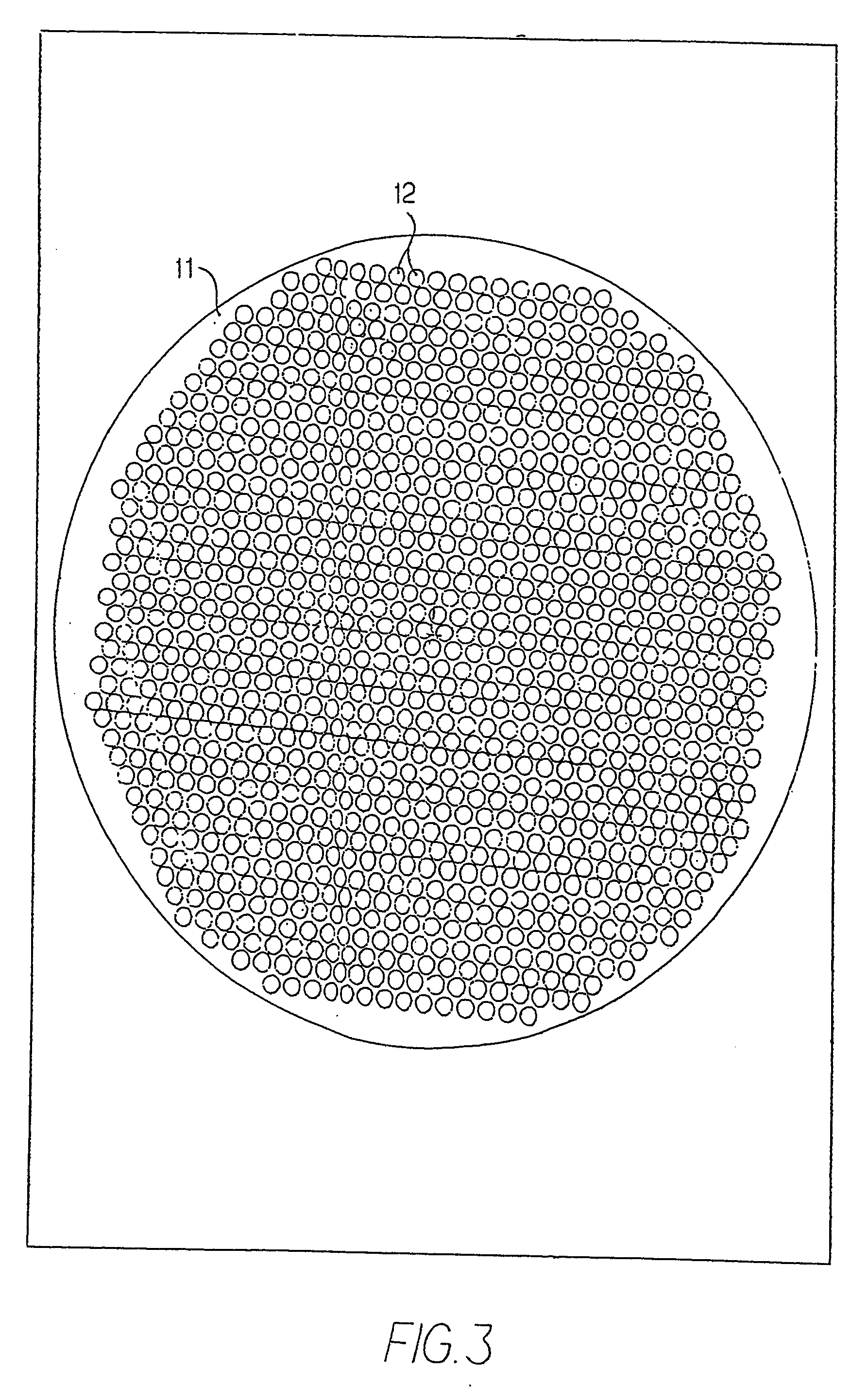
[0041]FIG. 1 is a schematic view of a chemical reactor 10, including a plurality of tubes 12, which hold catalyst. The tubes 12 extend downwardly from an upper plate (or tube sheet) 11 and are open on the bottom, except for clips (not shown), which may be used to prevent the catalyst from falling out the bottom of the tubes. A manway 14 provides access for workers to get into the reactor 10. A worker 16 is shown inside the reactor 10, measuring the back pressure in the catalyst tubes 12. In other reactors, the top may be fully removable, providing improved access.

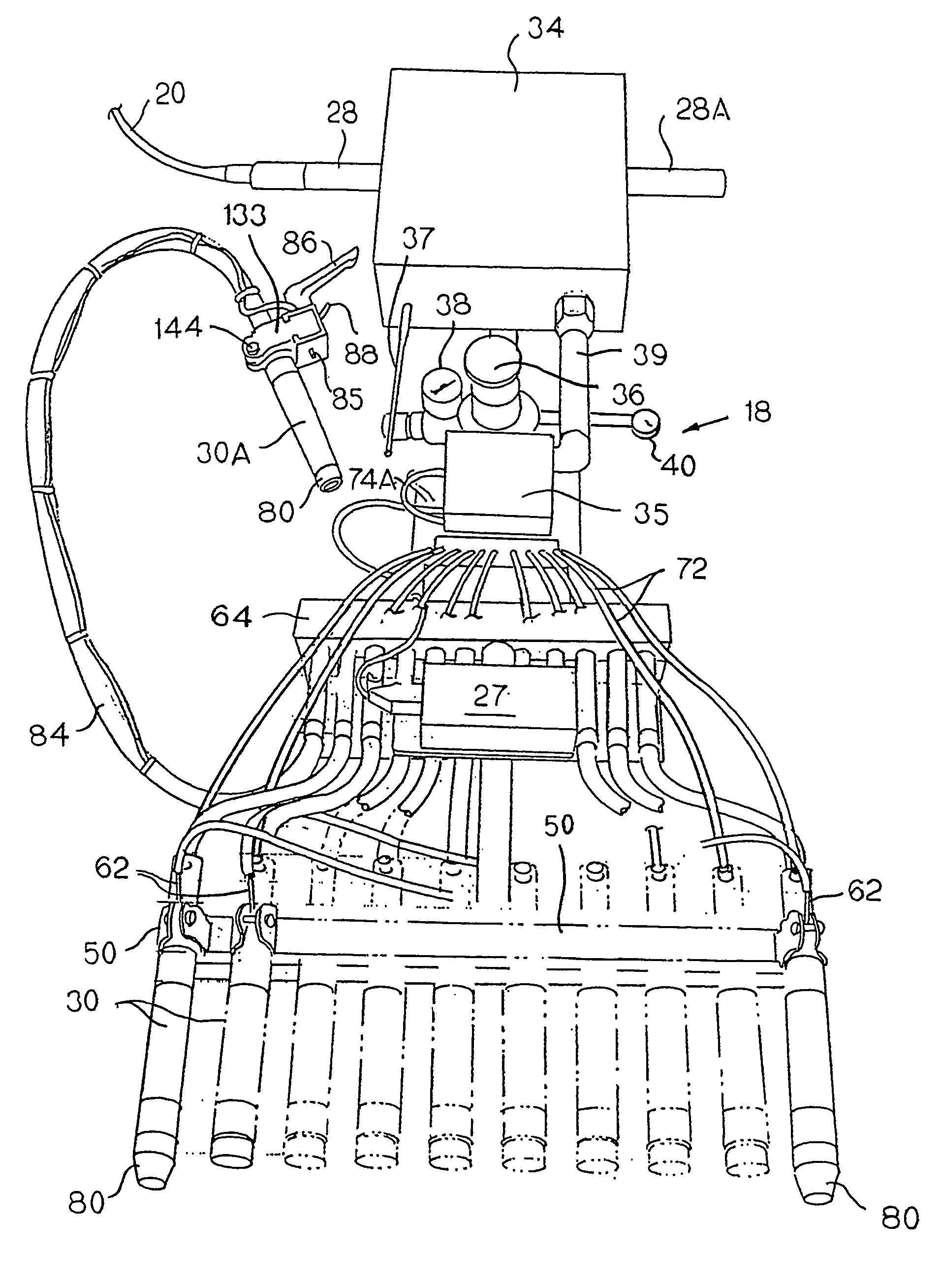
[0042]FIG. 2 shows the worker 16 standing on the plate 11 and operating a hand-held wand 18, which measures the back pressure in the tubes 12. The details of the wand 18 are shown better in FIG. 4. The wand includes a handle 28, a wand body 26, and a plurality of injector tubes 30 rigidly mounted together to form a single portable unit which is sufficiently rigid that the injector tubes can be inserted simultaneously into ...


PUM


Abstract

A device and method for measuring the back pressure in chemical reactor tubes includes many automated features. Inflatable tube seals may be automatically inflated. The device may measure several tubes at once. It may transmit data electronically to a remote computer for analysis and graphic display.

Description

[0001] This application is a continuation-in-part of U.S. patent application Ser. No. 10 / 097,908, filed Mar. 14, 2002, and claims priority from and incorporates by reference U.S. Provisional application Ser. No. 60 / 276,780, filed Mar. 16, 2001 and U.S. Provisional application Ser. No. 60 / 314,859, filed Aug. 24, 2001.BACKGROUND [0002] The present invention relates to tubes in chemical reactors, and, in particular, devices and methods for measuring the back pressure in the tubes and for blowing dust out of the tubes. [0003] Many chemical reactors use a catalyst as part of the reaction process. The catalyst material frequently is coated onto or contained in a substrate which is packed in tubes within the reactor. The reactants flow through the tubes and out the open ends of the tubes, reacting in the presence of the catalyst to form the products of the reaction. It is desirable to be able to measure the packing of catalyst within the tube in order to determine whether the tube will fun...

Claims


Application Information

Patent Timeline
Patent Type & Authority Applications(United States)
IPC IPC(8): G01M19/00G01M99/00B01J8/00B01J8/06
CPCB01J8/001G01N33/0004B01J8/06B01J19/0073B01J2208/0007B01J2208/00539B01J2208/00584B01J2208/00654B01J2208/00769B01J2208/00805B01J2219/002B01J2219/00213B01J2219/0024G01L19/083G01L19/086B01J8/008
Inventor JOHNS, CLIFFORD L.SYMPSON, DANIEL D.
Owner TUBEMASTER INC
Why Eureka
Try Eureka